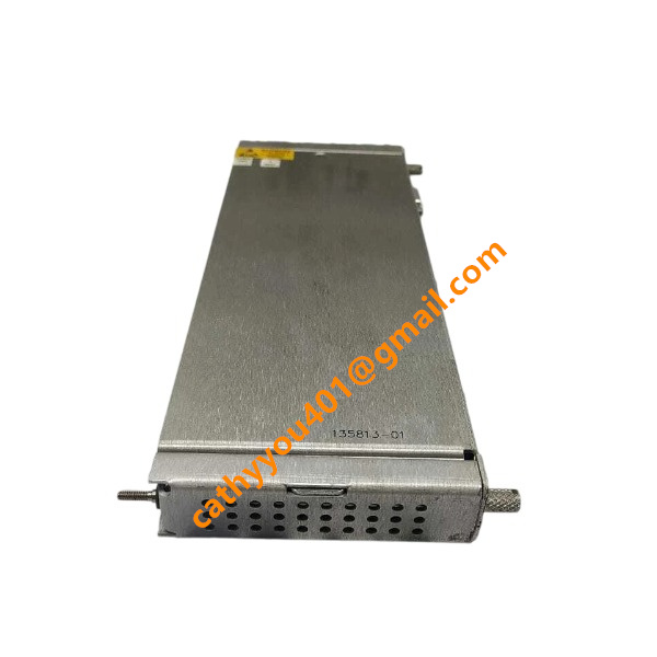
2D5F0DD710864F35B527BDF49779F9DC.jpg)







Description
-
BrandBently Nevada
-
Model3500/70 135489-03
-
Product Name3500/70 Velomitor I/O Module
-
Place of OriginUnited States
-
Customs HS Code8538900000
-
Power Supply7.0 W to 7.7 W
-
Dimensions241.3 mm (height) × 24.4 mm (width) × 241.3 mm (depth)
-
Weight0.46 kg
-
Operating Temperature-40°C to +70°C
-
Storage Temperature-55°C to +90°C
-
Warranty12 month
-
Product Statusnew
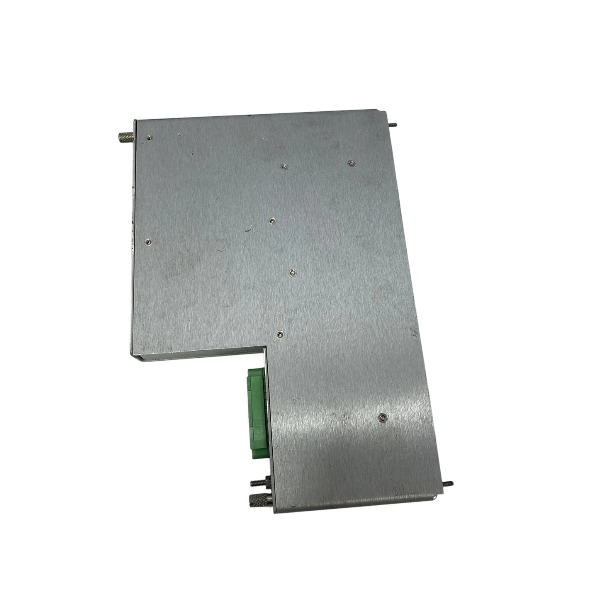
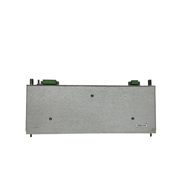
Bently Nevada 135489-03 I/O Module with Internal Barriers
Module Type: 4-channel Velomitor I/O module with onboard terminations, designed for use with 3500/42, 3500/70 and 3500/72 monitor modules
Power Supply: Powered through the 3500 rack backplane
Channel Configuration: 4 independent Velomitor input channels
Features integrated intrinsically safe barriers to accommodate transducers installed in hazardous locations
Signal Bandwidth: 30 kHz
Diagnostics: Channel fault detection, sensor fault and wiring fault monitoring
Compatible Sensors: Velomitor seismic sensors for casing vibration measurement
System Compatibility: Fits the standard 3500 machinery protection rack; standard I/O modules and barrier-equipped I/O modules may be installed within the same rack
Relative Humidity: 5% to 95%, non-condensing
Function: Performs signal conditioning on seismic velocity signals; delivers intrinsic safety protection for field sensors without standalone external barriers; sends processed vibration data to the paired host monitor module
Compliance: Engineered for rotating machinery protection and meets hazardous area certification requirements

Bently Nevada 135489-03 I/O Module with Internal Barriers Installation Procedure
Pre-installation preparation
Inspect the module for physical damage and confirm the part number complies with design specifications. Prepare an anti-static wrist strap, insulated screwdriver, multimeter and qualified wiring tools. Ensure the 3500 rack is completely de-energized and measure zero voltage on the backplane. Confirm that a 3500/04 IS Earthing Module is fitted in the rack, as it is a prerequisite for all I/O modules with internal barriers. Check that the site environment satisfies temperature and humidity requirements, and is free of corrosive vapors and severe electromagnetic interference.
Static protection and rack slot selection
Fit the anti-static wrist strap and connect it to a reliable instrument ground on the cabinet. Choose a standard vacant slot inside the 3500 rack for module installation. Where practicable, cluster barrier-type modules together. Maintain a minimum clearance of 50 mm between field cables for hazardous areas and control cables for safe areas.
Module insertion and mechanical mounting
Align the module with the rack guide rails, slide it horizontally into the designated slot, and push steadily until the connector fully engages with the backplane. Lock the ejector latches and fasten the retaining screws on the front panel to secure the module against vibration.
Field wiring and intrinsic safety termination
Connect Velomitor seismic sensors to the internal screw terminals of the module in accordance with official wiring schematics. Separate hazardous-area sensor cables from high-voltage AC power cables. Terminate cable shields per specification; bond shields to a single instrument grounding point and refrain from multi-point grounding. Ensure intrinsic safety parameters for the hazardous zone are not exceeded.
IS grounding connection
Verify that the 3500/04 IS Earthing Module is correctly wired to the dedicated intrinsic safety earth. The IS grounding circuit shall be isolated from protective equipment ground in compliance with hazardous area certification rules.
Post-wiring inspection
Check that all terminal connections are tight, and test sensor loops for short circuits and open circuits. Make certain there is no cross-connection between safe and hazardous circuits. Organize cables neatly and fix them with cable ties.
Power-up and hardware self-test
Re-energize the rack only after wiring has been fully verified. Monitor the LED indicators on the module front panel. Ensure no fault alarms appear during automatic self-test. Launch the 3500 configuration software to identify the module and validate communication with its matched monitor module (3500/42, 3500/70 or 3500/72).
Channel configuration and function verification
Configure the four Velomitor input channels within the rack configuration software, including sensor type, measuring range and alarm setpoints. Carry out signal injection tests on every channel to validate measurement accuracy. Confirm that diagnostics for sensor faults and wiring faults operate normally. Save and create backups of the final rack configuration.
Final check
Operate the system under continuous monitoring to verify stable vibration data transmission without intermittent failures or false diagnostic alerts. Retain wiring documentation, test records and configuration files for project handover.

3500/22-01-01-01
3500/22 288055-01
1900/65A
24765-02-01
3500/91-01-01-01
3500/44-02-01
TK-3E
177313-02-01
1900/65A-01-01-04-CN-00
2300/20-CN


.jpg)

.jpg)