





.jpg)
1BF50F082EDD4CB2A78E753065E9F54D.jpg)
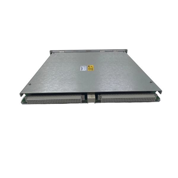
.jpg)







Description
-
BrandBently Nevada
-
Model3500/22M 138607-01
-
Product NameTransient Data Interface (TDI) Module
-
Place of OriginUSA
-
Customs HS Code85423190
-
Power Supply0.43 A
-
Dimensions241.3 mm × 24.4 mm × 241.8 mm
-
Weight0.91 kg
-
Operating Temperature-20°C to +70°C
-
Storage Temperature-40°C to +85°C
-
Warranty12 month
-
Product Statusnew
Fault Diagnosis Methods for Bently Nevada 3500/22M (138607-01)
Examine the physical mounting of the module and rack power supply, and check backplane connectors for oxidation, pin damage or loose contact.
Evaluate module operating conditions through front-panel LED indicators. Determine hardware failures, configuration mistakes and communication anomalies based on the OK, status and network LEDs.
Establish a local connection with the configuration software via the front USB port, and retrieve rack status, event logs and fault codes to conduct initial fault localization.
Inspect the rear Ethernet path when communication fails. Verify cable continuity, switch port status, IP settings and firewall configurations.
Analyze the system event list and alarm logs within System 1 software to confirm if faults originate from the TDI module, other monitor modules or field sensor loops.
Validate consistency of the rack configuration. Confirm matching hardware layout, completed parameter download and valid licenses on the Channel Enabling Disk for transient waveform capture.

Execute a power cycle or soft reset of the module, and check if intermittent communication or initialization faults can be resolved.
Isolate faults by swapping module slots and testing with spare units, to differentiate failures of the backplane slot from internal module hardware defects.
Test the transient data acquisition function and verify that synchronous keyphasor signals and dynamic waveforms can be uploaded to System 1 properly.
Check the compatibility of firmware versions. Reinstall the correct firmware if malfunctions arise from unsuccessful firmware upgrades.
Inspect grounding and shielding of signal cables to suppress ground loop interference that leads to fluctuating readings and sporadic faults.
Document fault symptoms, LED states and event details. Cross-reference findings with the official manual and replace the module once permanent hardware failure is confirmed.
Real-time Monitoring Procedures for Bently Nevada 3500/22M 138607-01
Ensure the 3500/22M TDI module is correctly installed inside the 3500 rack, with reliable backplane connection and stable rack power input.
Finish rack hardware setup using 3500 Configuration Software, including module slot allocation, network parameter settings and channel configuration for monitor modules.
Configure a static IP address for the 3500/22M, then link its Ethernet port to the control network or directly to the workstation installed with System 1 software.
Download the verified configuration to the 3500 rack, wait for module initialization, and confirm the OK LED stays on as normal.
Connect field devices such as vibration transducers, displacement probes and keyphasor sensors to their matching monitor modules in the rack.
Start System 1 on the monitoring workstation and build network communication with the 3500/22M TDI module.

Create machinery assets in System 1, associate them with measurement channels, and define alarm thresholds for vibration, rotational speed and displacement.
Enable real-time data streaming to continuously acquire static process values, dynamic vibration waveforms and keyphasor pulse signals.
Observe live readings, trend graphs, spectrum charts and orbit plots through the real-time interface of System 1.
Set up visual alarm alerts. The system will mark abnormal conditions and trigger instant alarms when measurements go beyond predefined limits.
Turn on ongoing event and waveform recording to capture transient abnormal signals during normal machinery operation.
Periodically check network delay and module diagnostic status to eliminate communication loss or signal interference that disrupts monitoring.
Store real-time trend templates and display layouts to facilitate fast assessment of machine health during regular inspections.

3500/22-01-01-01
3500/22 288055-01
1900/65A
24765-02-01
3500/91-01-01-01
3500/44-02-01
TK-3E
177313-02-01
1900/65A-01-01-04-CN-00
2300/20-CN


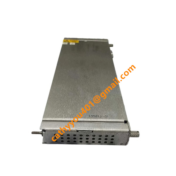

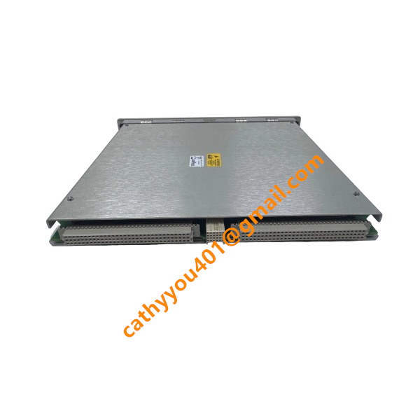
.jpg)
.jpg)







