





8411BBA223AE4847B55D85ECB895B091.jpg)
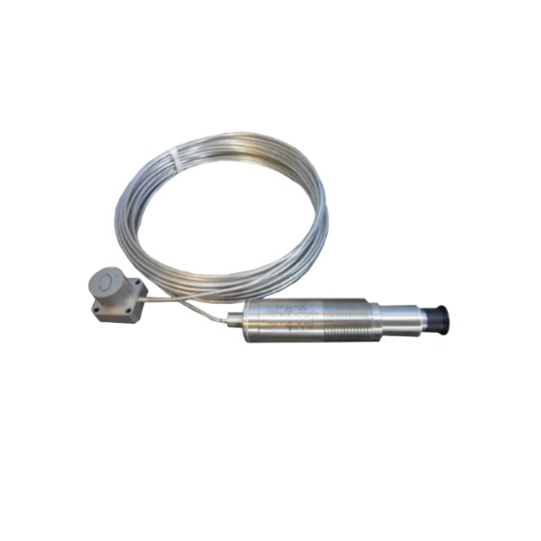







Description
-
BrandBentley Nevada
-
Model330752-25-CN
-
Product Name3300 XL 8mm Probe Extension Cable
-
Place of OriginUnited States
-
Customs HS Code8544422100
-
Power Supply24 VDC
-
DimensionsCable length 25 meters, outer diameter 6.3 mm
-
Weight1.9 kg
-
Operating Temperature-50 ℃ ~ +125 ℃
-
Storage Temperature-55 ℃ ~ +150 ℃
-
Warranty1 year
-
Product Statusnew
Input & Output of Bently Nevada 330752-25-CN (High-Temperature Velomitor)
Input
Power supply input: 24 VDC-28 VDC, with a maximum rated input current of 120 mA. DC power is fed from the Bently Nevada 3500-series or equivalent monitor rack to energize the velomitor’s on-board signal-conditioning circuitry.
Mechanical input: Vibration velocity originating from rotating-machine casings. Its built-in piezoelectric sensing element translates mechanical vibration displacement into a raw charge signal, serving as the physical input for the complete sensor assembly. The sensing head supports a maximum surface operating temperature of 400 °C.
Output
Primary analog vibration output (AC dynamic signal overlaid onto a DC bias voltage):
Bias DC output voltage: -12 VDC ±2 VDC. This steady-state DC level acts as a reference for monitor channel diagnostics, enabling sensor health evaluation and cable-fault detection.
Dynamic AC vibration signal: Sensitivity equals 5.7 mV/mm/s (145 mV/in/s) with ±5 % tolerance. AC signal amplitude varies proportionally with casing vibration velocity.
Frequency response: 15 Hz-2000 Hz (±3.0 dB); 20 Hz-1000 Hz (±0.9 dB).
Signal transmission: The composite signal consisting of DC bias plus AC vibration is conveyed to the monitor rack input channel via the integral 2.5-meter high-temperature hard-line cable.
Diagnostic output capability: The monitor continuously monitors the -12 VDC bias value. Should open-circuit faults, short-circuit conditions or sensor degradation arise, bias voltage will drift outside its permitted band and initiate a sensor-fault alarm at the monitor unit.

Commissioning Procedure for Bently Nevada 330752-25-CN Extension Cable (3300 XL Proximity System)
Pre-Installation Visual Inspection
Examine the probe, extension cable, connectors and junction boxes for physical damage, cracks, insulation wear and corrosion. Confirm the part number 330752-25-CN and cable length comply with project design specifications. Inspect connector pins for dirt, debris or bent pins. Ensure the probe mounting hardware is sturdy, clean and free of paint, rust and residual foreign particles.
Continuity and Insulation Resistance Test
Disconnect all field cabling from the monitor rack. Test signal-wire continuity and document resistance readings. Use a megohmmeter to carry out insulation resistance testing between signal conductors and the cable shield, ensuring measured values satisfy OEM requirements. Verify shield integrity; the cable shield shall be grounded exclusively at the monitor-rack end, with no additional grounding points on the field side.
Mechanical Installation
Install the 3300-XL proximity probe onto the machine housing in accordance with the specified torque value. Align the probe perpendicular to the observed shaft surface. Select non-resonant mounting brackets. Maintain the minimum permissible bending radius for the extension cable; avoid pulling, twisting or compressing the cable assembly. Properly seal field connectors against dust and moisture. Separate signal cabling from high-power AC wiring to minimise electromagnetic interference.
Field Wiring Termination
Terminate probe signals and shield conductors to the matching channel terminals on the Bently Nevada 3500-series or compatible monitor rack. Double-check wiring polarity and terminal torque. Strictly implement single-point grounding for cable shields. Cap and seal any unused cable ends.
Pre-Power-On Verification
Ensure site personnel keep clear of energised zones. Confirm rack supply voltage falls within the rated operating range. Rule-out short-circuits between signal conductors and between signal circuits and protective earth. Verify reliable protective-earth connection for the monitor rack.
Power-Up and Channel Health Check
Apply power to the monitor rack. Access the target measurement channel via the unit front-panel interface or System 1 software. Observe the channel OK status indicator. Confirm no fault, sensor break, under-range or over-range alarms are active. Review raw DC gap voltage readings to validate normal operating status.
Channel Parameter Configuration
Select 3300-XL proximity transducer as the sensor type in monitor settings. Define measurement units, full-scale range, alert and danger threshold values based on machine-protection specifications. Configure time-delay parameters for alarm relays. Store validated configuration inside the rack and export a backup configuration file.
Static Signal Logging
Record gap-voltage readings while the unit remains at standstill. Document raw values, background noise levels and overall channel health. Elevated noise suggests electromagnetic interference, poor connector contact or improper mounting; carry out troubleshooting where anomalies occur.
Dynamic Verification During Machine Start-Up
Initiate machine start-up and continuously monitor real-time gap, shaft vibration and thrust position trends. Compare live measurements against baseline reference data. Watch for intermittent signal loss or signal drift. Where site conditions allow, perform alarm relay simulation tests. Confirm correct relay signal transmission to DCS/SCADA systems.
Final Documentation and Hand-Over
Compile test records including measured values, configured parameters, insulation-test results and wiring inspection logs. Retain configuration backup files. Apply clear identification labels for probes, extension cables and monitor channels. Complete the official commissioning report and deliver documentation to site operating staff.
Post-Commissioning Maintenance Note
The 330752-25-CN extension cable does not require regular on-site calibration. Conduct visual checks for cable degradation and connector sealing integrity during scheduled equipment outages.

3500/22-01-01-01
3500/22 288055-01
1900/65A
24765-02-01
3500/91-01-01-01
3500/44-02-01
TK-3E
177313-02-01
1900/65A-01-01-04-CN-00
2300/20-CN







