





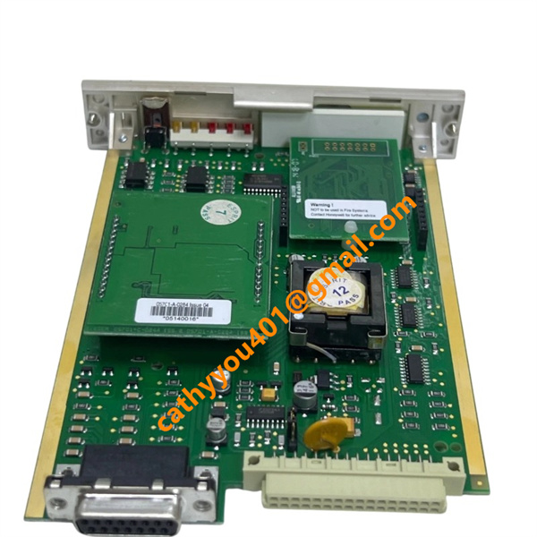
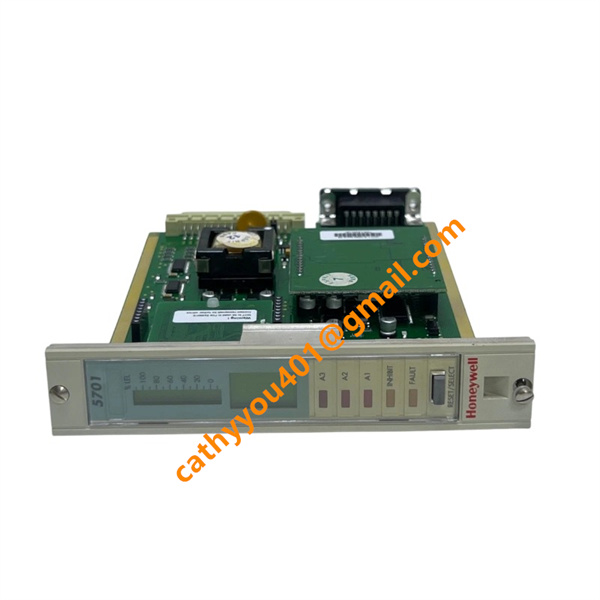







Description
-
BrandHONEYWELL
-
Model05701-A-0302
-
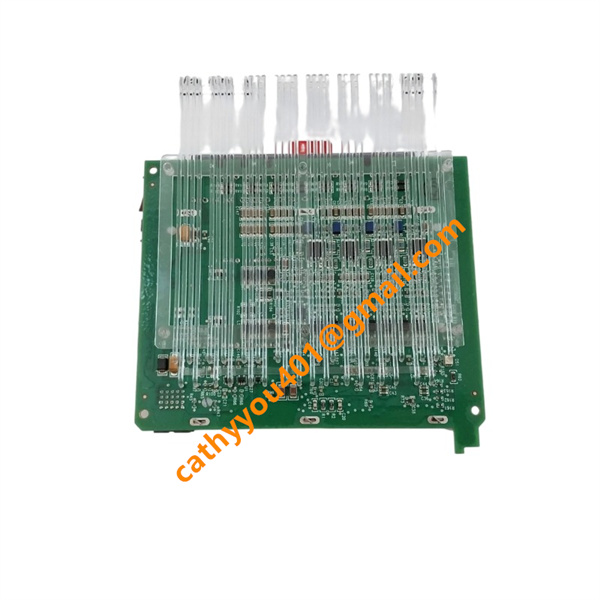
Product NameSystem 57 Single-Channel Catalytic Gas Detection Control Card
-
Country of OriginUnited States
-
HS Code8537101190
-
Dimensions170mm×25mm×112mm
-
Weight0.165 kg
-
Operating Temperature-40 ℃ ~ +70 ℃
-
Storage Temperature-40 ℃ ~ +85 ℃
-
Power Supply24VDC
-
Warranty12 month
-
Product StatusNew and original
HONEYWELL 05701-A-0302 Complete Product Specification
Core Technical Parameters
1. Rated Working Voltage: 24 VDC (allowable fluctuation range: 18 VDC ~ 32 VDC wide voltage input)
2. Power Consumption: 3.75 W typical (catalytic sensor mode); 3.25 W typical (4-20mA signal mode)
3. Operating Current: Typical 0.156 A @ 24 VDC rated voltage
4. Measurement Accuracy: ±0.5% FS (Full Scale)
5. Electronic Drift: Less than ±2% per 6 months
6. Alarm Setting Resolution: Adjustable in 1% FSD steps
7. Display Configuration: 4-part LCD (25-segment analog bar graph + 4-digit numeric readout + status message + function icons)
8. Signal Input Types: Catalytic bridge mV signal / 4-20mA analog current signal
9. Output Interface: A1/A2/A3 alarm relays, fault relay, Honeywell UPB internal system bus
10. Protection Class: IP20 (only for cabinet internal installation)
11. Relative Humidity: 5% – 95% non-condensing
12. Installation Method: Standard half 19-inch rack mounting for System 57 cabinet backplane

05701-A-0302 Standard Wiring & Connection Method
1. Backplane Power Wiring
Insert the 05701-A-0302 module into the designated slot of the System 57 cabinet backplane; the cabinet backplane will automatically provide 24VDC power and UPB bus communication;
Lock the module fixing screws tightly to ensure reliable electrical contact between the card and backplane.
2. Field Gas Sensor Wiring
Catalytic bead sensor terminals: Connect 2-wire or 3-wire catalytic bridge sensor shielded cables to the front field wiring terminals;
4-20mA transmitter terminals: Connect standard 2-wire 4-20mA gas transmitter current loop cables separately.
3. Alarm Relay Output Wiring
A1/A2/A3 alarm relay terminals: Connect to external audible and visual alarms or PLC signal input terminals;
Fault relay terminals: Connect to upper monitoring system for equipment fault feedback signal collection.
4. Wiring Precautions
All wiring operations must be completed under the overall power-off state of the System 57 cabinet;
Field sensor cables must use shielded twisted pairs, with the shielding layer grounded only at the cabinet end to eliminate interference;
Do not bundle sensor signal cables with high-current power cables;
After wiring, perform channel address configuration and sensor calibration via the front panel operation button before formal operation.

HONEYWELL 05701-A-0302 Product Advantages
1. Professional catalytic sensor dedicated drive circuit, stable signal acquisition with extremely low long-term drift, reducing regular calibration frequency;
2. Three-stage independent alarm output plus fault self-test function, capable of real-time sensor aging diagnosis to avoid missing alarms;
3. Integrated high-definition multi-mode LCD panel, on-site direct reading of gas concentration without external display equipment;
4. Wide-range 18~32VDC power supply design, strong anti-power fluctuation ability, suitable for unstable industrial power environments;
5. SIL2 safety certification, meeting strict industrial safety standards for hazardous area gas monitoring;
6. Hot-swappable rack module design, replacement and maintenance will not affect the operation of other gas detection channels;
7. Sealed PCB and anti-electromagnetic interference structure, stable operation in strong electromagnetic industrial sites;
8. Native compatibility with Honeywell mainstream DCS systems, seamless data uploading without additional conversion gateways;
9. Global Honeywell technical support and complete spare parts supply chain, long-term industrial project applicability.