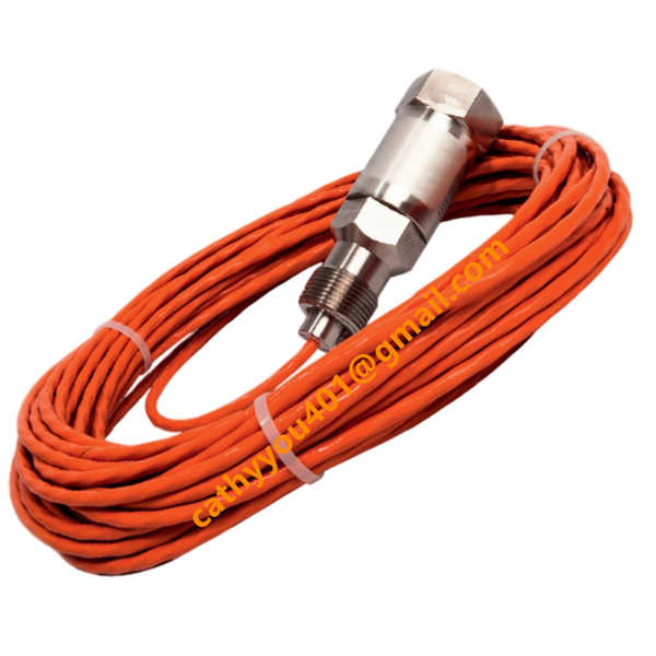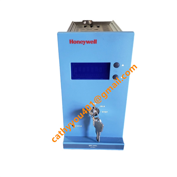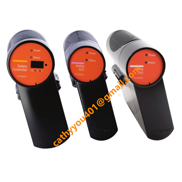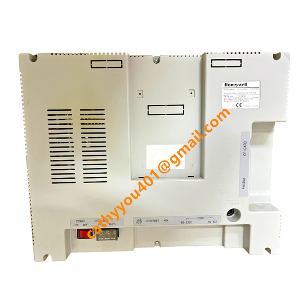












Description
-
BrandHoneywell
-
ModelLG1093AA36
-
Product NameUltraviolet (UV) Flame Sensor / Flame Detector
-
Country of OriginUnited States
-
HS Code9027100090
-
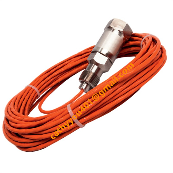
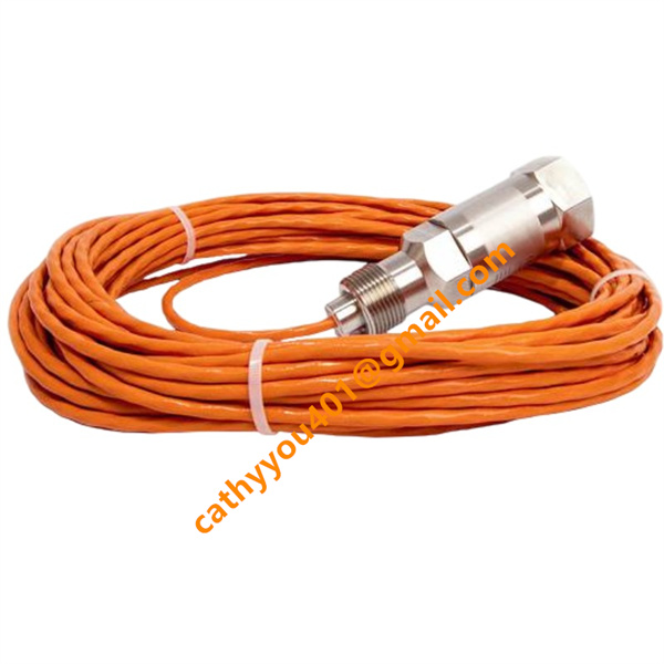
Dimensions36 feet (Approximately 11 meters) of integrated Teflon-shielded cable with a 1-inch external conduit thread.
-
Weight3.8 kg
-
Operating TemperatureUp to 400 °F
-
Storage Temperature-40 °C to +85 °C
-
Power Supply24VDC
-
Warranty12 month
-
Product StatusNew and original
Honeywell LG1093AA36 Technical Specifications and General Information
Explosive Atmosphere Approvals: Designed and certified to meet explosion-proof standards, including Factory Mutual (FM) approval and European CE/ATEX directives for hazardous locations.
Input and Sensing Specifications
Sensing Technology: Geiger-Mueller phototube detector.
Optical Spectral Response Range: 1800 to 2600 Angstroms (180 nm to 260 nm), isolating the UV signature of a hydrocarbon flame.
Radiation Target: Hydrocarbon fuel combustion emissions.
Response Sensitivity: Exceptionally high sensitivity, delivering a typical flame response or flameout detection time of 0.1 seconds.
Reliability Metrics: 10,000 hours Mean Time Between Failures (MTBF) with a two-year shelf life.
Output and System Signal Specifications
Output Signal Type: High-frequency pulse output signal directly proportional to the perceived intensity of the ultraviolet radiation.
Signal Transmission Distance: Capable of transmitting clean pulse signals through the integrated cable to a remote system amplifier located up to 1,000 feet (305 meters) away.
System Power/Amplifier Compatibility: Drives are traditionally powered via matched Honeywell EG1033 series amplifiers, supporting system configurations of 28 Vdc, 20–35 Vdc, or 115 Vac.

Honeywell LG1093AA36 Key Product Advantages
Decades of Proven Gas Turbine Performance: Formally qualified component with over 35 years of application history on General Electric (and GE licensee) industrial turbines.
Solar Blind Sensing: The internal phototube ignores background infrared, sunlight, and red-hot turbine metal components, eliminating false flame indications.
Extreme Environment Construction: Outfitted with an explosion-proof enclosure, high-pressure viewing window, and robust Teflon-shielded cabling capable of enduring intense heat, moisture, and vibrations.
High-Speed Fault Isolation: Sub-second response times allow the host turbine control system to immediately cut fuel lines during a flameout event, preventing explosive unburned fuel accumulation.

Honeywell LG1093AA36 Comprehensive Wiring Method and Steps
Installation and electrical hookups must only be performed when the combustion chamber is entirely powered down, depressurized, and cooled.
Mechanical Mounting: Thread the sensor head onto the 3/4-inch NPT viewing port or sight pipe directed at the primary combustion zone. Ensure the line of sight is clear and the window assembly is properly sealed against the 150 psig pressure limits.
Conduit and Cable Routing: Route the built-in 36-foot Teflon-shielded cable away from high-voltage igniter leads and sharp manifold corners. Use the 1-inch external conduit thread on the cable assembly to lock it into a flexible, liquid-tight metal conduit for physical defense.
Amplifier Terminal Allocation: Bring the conductor ends to the remote junction box or control panel containing the Honeywell EG1033 amplifier. Ensure the power to the amplifier chassis is switched off during this step.
Signal Wire Connection: Connect the designated positive and negative signal leads from the LG1093 sensor cable into the corresponding channel input terminals on the amplifier. This channels the pulse output train safely into the monitoring circuitry.
Shield Grounding Protection: Properly terminate the outer braided cable shield to the system ground bus or the specific shield terminal (such as on the EG1033AD model) to suppress electromagnetic interference (EMI) caused by surrounding heavy machinery. Do not loop ground paths.
Pre-Operational Validation: Confirm that the cable insulation is uncompromised and all connections are snug. Power up the 24Vdc/115Vac control supply to the amplifier and check the status LEDs to verify proper sensor continuity prior to initiating the fuel ignition sequence.