





.jpg)
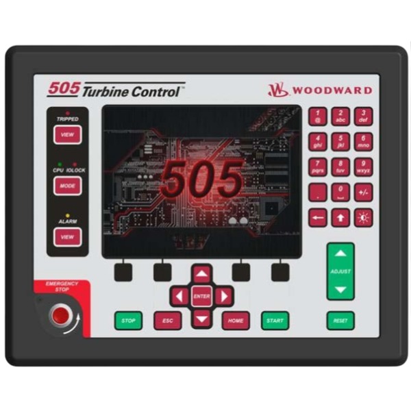







Description
-
BrandWOODWARD
-
Model8200-131
-
Product Name505XT Digital Turbine Controller
-
Place of OriginUnited States
-
Customs HS Code85389000
-
Power Supply18V DC to 36V DC
-
Dimensions280mm × 220mm × 75mm
-
Weight2.1kg
-
Operating Temperature-20°C to +65°C
-
Storage Temperature-40°C to +85°C
-
Warranty1 year
-
Product Statusoriginal
Commissioning Procedure for Woodward 8200-131 (505XT Steam Turbine Controller)
1. Pre-commissioning Inspection and Preparation
Carry out LOTO safety procedures prior to wiring and power application. Inspect controller mounting, cabinet earthing and cable routing. Verify all wiring connections including speed pickups, 4–20 mA analog inputs, actuator outputs, discrete inputs, trip relay outputs and communication cables. Prepare Control Assistant software, configuration cable, multimeter, signal generator and turbine technical documentation. Confirm the 18–32 VDC isolated control power supply is stable and compliant with requirements.
2. Power-on and Self-diagnosis
Energize the controller with DC power. Observe the power indicator and on-screen power-up self-test on the local display. Review fault and alarm messages. Clear historical trip records once no hardware defects are identified. Connect a laptop through the service port or Ethernet to establish communication with Control Assistant, and back up the factory or existing configuration file.
3. Controller Configuration Setup (Configuration Mode, I/O Lock Activated)
Access configuration mode by entering the required password. Select turbine application type, speed range, actuator type and I/O definitions. Configure rated speed, overspeed trip threshold, idle speed, acceleration ramp rate, speed setpoint limits and protection parameters. Set scaling for analog inputs, assign functions to discrete inputs and define relay output logic. Configure communication parameters including Modbus TCP/RTU and CAN bus for data exchange with SCADA and DCS systems. Download the completed configuration to the controller and perform a reboot.
4. I/O Signal Verification with I/O Lock Enabled
Test speed pickup channels by injecting a simulated frequency signal and validate that the displayed speed reading matches the input value. Apply test signals to all 4–20 mA analog inputs using a signal source to verify readings and scaling accuracy. Force discrete input states and check corresponding status indications on the controller. Force relay outputs to confirm proper actuation of trip, alarm and auxiliary contacts. Calibrate the actuator analog output: set 4 mA for valve fully closed and 20 mA for valve fully open, and record stroke data and position feedback.
5. Protection Logic Static Test
Simulate protective trip conditions including overspeed, low lube oil pressure, high vibration and turbine emergency stop. Confirm the controller issues a trip command, the actuator moves to its safe position and the trip relay operates correctly. Verify that trip logs, fault codes and time-stamped event records are generated as expected. Reset the trip condition and return the controller to ready status after each test case.
6. Dynamic No-load Test (Turbine Barring / No Steam Condition)
Release the I/O lock and switch the controller to ready mode. Perform a full valve stroke test to inspect actuator response, operational stability and consistency of position feedback. Test local and remote speed setpoint adjustment, ramp functions and limit enforcement. Validate preliminary speed PID gain settings to prevent system oscillation.
7. Turbine Start and On-load Commissioning
Acknowledge and reset all active alarms and trips, and confirm all startup permissive conditions are met. Initiate the turbine startup sequence following the designated startup curve. Monitor speed rise, acceleration rate and valve movement in real time. Tune PID gains and stability parameters at idle speed and rated speed. Test speed regulation, load control, droop characteristics and setpoint tracking performance. Verify cascade control, auxiliary PID loops and extraction/backpressure control functions where applicable.
8. Interlock and Remote Communication Test
Validate DCS remote setpoint, remote trip and enable signals. Check real-time data transmission over the communication link, including rotational speed, valve demand, temperature, pressure and fault status. Confirm remote alarm acknowledgement and reset functions operate reliably.
9. Stability and Long-run Observation
Operate the turbine across its normal load range for stability assessment. Record speed deviation, valve fluctuation and dynamic response during load transitions. Fine-tune PID parameters if hunting or overshoot is observed. Monitor thermal drift and intermittent faults throughout continuous operation.
10. Final Documentation and Handover
Archive the final configuration file, parameter report, calibration records and test logs. Document trip setpoints, PID tuning values and communication register mapping. Export event logs and the alarm matrix. Deliver the configuration backup and commissioning report to the site operation team.

Control Logic of Woodward 8200-131 (505XT Steam Turbine Controller)
Type: Digital governor controller for single-valve, extraction or admission steam turbines
1. Overall Logic Architecture
The 505XT adopts closed-loop digital control centered on valve demand calculation. It acquires field signals including speed, pressure, temperature, discrete permissive and trip inputs. Multiple independent PID loops compute demand values, and a priority selector determines the final valve command to drive the actuator. The complete logic covers startup sequence, closed-loop regulation, limiting functions, bumpless mode transfer and turbine trip protection.
Core principle: All control targets are converted into valve opening demand. Trip protection logic carries the highest priority and overrides all regulatory loops.
2. Speed / Load Primary PID Loop (Core Loop)
Speed measurement: Captures frequency signals from one or two speed pickups, converts frequency into turbine RPM, and diagnoses faults such as pickup loss or abnormal signals.
Speed control mode: The PID compares actual speed against the speed setpoint and adjusts the steam valve to stabilise turbine speed. It supports local setpoint, remote 4–20 mA setpoint and setpoint via communication channels. Integrated functions include adjustable acceleration ramp, maximum speed limit and critical speed avoidance bands.
Load control mode (droop control): For generator-driven turbines, the controller switches to load PID. It takes generator power as the process variable and regulates turbine load with configurable droop. Speed serves as an over-limit protection; excessive speed deviation will override load control.
PID tuning: Separate acceleration PID for startup conditions and running PID for normal operation. The OptiTune auto-tuning function is available.
3. Auxiliary, Cascade and Extraction / Admission PID Logic
Cascade PID: Applied for header pressure or backpressure control. The output of cascade PID acts as the setpoint for the speed/load PID. Bumpless transfer is supported between cascade mode and direct speed mode.
Auxiliary PID 1 & 2: Independent closed auxiliary loops for parameters such as exhaust pressure and gland steam pressure. Auxiliary demand is incorporated into valve calculation through limiters.
Extraction / Admission logic (key feature of 505XT): Equipped with two valve actuators, namely the throttle valve and extraction/admission valve. A ratio limiter decouples speed and extraction pressure based on the turbine steam map. The controller distributes valve commands to maintain both speed and extraction pressure within the turbine operating envelope and eliminate cross-coupling interference between the two controlled variables.
4. Startup Sequence Logic
The controller implements state-machine sequential logic: Ready → Pre-start permissive check → Crank / Barring → Speed ramp up → Idle speed hold → Synchronisation / Load control.
Pre-start condition check: All discrete permissive inputs (lube oil pressure, vacuum, generator breaker status, emergency reset signal) must be satisfied.
Speed ramp: The controller follows the configured acceleration rate. It holds speed at idle and allows operators or DCS to continue ramping to rated speed.
Synchronisation assist: Generates speed bias signals for generator synchronisation. After the generator breaker closes, the controller automatically transfers to load control.
Hold function: The speed ramp pauses when permissive signals are lost and resumes once signals recover.
5. Limiter & Priority Selection Logic
Demand outputs from all PID loops pass through a priority selection algorithm, where the lowest demand value governs the final valve output. Typical limiters include:
Maximum valve opening limiter
Upper and lower load limits
Pressure override limiter
Temperature override limiter
Rate-of-change limiter to restrain abrupt valve movement and mechanical shock
This mechanism ensures coordinated operation of multiple control functions without conflict.
6. Mode Transfer Logic (Bumpless Transfer)
It supports smooth switching between local and remote setpoint, speed mode and load mode, as well as cascade and direct speed control. Prior to switching, the controller automatically tracks the active demand of the target loop. No step change occurs in the valve command upon transfer, preventing turbine fluctuations.
7. Protection & Trip Logic (Highest Priority)
Trip logic operates asynchronously and overrides all regulatory loops. Once a trip condition is latched, valve demand is forced to zero, the actuator closes the steam valve instantly, and trip relay contacts change state.
Trip input sources:
Overspeed trip (independent speed protection)
External ESD emergency stop discrete input
Process trips including low lube oil pressure, high vibration and low vacuum
Controller hardware faults and speed pickup loss
The trip latch requires manual reset after fault elimination. All trip events are time-stamped and stored in the event log.
8. I/O and Communication Logic
Analog inputs: 4–20 mA signals for speed setpoint, load feedback, pressure and temperature; with signal range verification and fault detection for open or short circuits.
Discrete inputs: Permissive signals, trip signals, remote start/stop and mode selection commands.
Analog / actuator output: 4–20 mA or dedicated drive signals for steam valves, with position feedback monitoring.
Relay discrete outputs: Trip relay, alarm relay and status indication relays.
Communication: Modbus TCP, Modbus RTU and CAN bus. The controller uploads speed, load, valve demand, alarms and fault codes to DCS/SCADA, and receives remote setpoints and commands. Communication loss does not trigger an automatic trip by default; fail-safe behaviour can be configured.
9. Diagnostic and Watchdog Logic
CPU watchdog: Initiates a safe trip if the main processor fails.
I/O channel diagnosis: Detects open circuits, short circuits and out-of-range analog signals.
Speed probe voting: Dual speed inputs can be set for voting logic. A single probe fault triggers an alarm instead of an immediate trip.
Event recorder: Captures all state transitions, alarms and trip sequences for post-fault analysis.
10. Man-Machine Interface Logic
The local HMI and Control Assistant software enable users to view measurements, modify setpoints, edit configurations and manually force I/O signals for static testing. Configuration mode activates the I/O lock, keeping outputs in a safe state to avoid unintended valve movement during commissioning.

1751-6058
5852-1062
8406-113
SPM-D11
9907-205
8237-1369
8237-1597
8404-1004
TG-13
9907-1183


.jpg)







