





D405432102154B6B8071BA1497A0CC43.jpg)
.jpg)
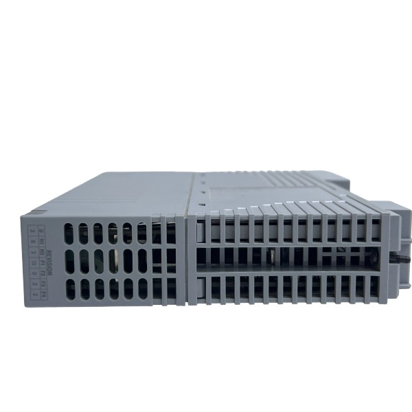







Description
-
BrandYOKOGAWA
-
ModelCP451-10
-
Product NameProcessor Module for CENTUM VP / CS3000 DCS
-
Place of OriginJapan
-
Customs HS Code8537101190
-
Power Supply0.8 A at 24 V DC
-
Dimensions152 mm × 51 mm × 203 mm
-
Weight0.74 kg
-
Operating Temperature0 ℃ ~ +55 ℃
-
Storage Temperature‑20 ℃ ~ +70 ℃
-
Warranty12 month
-
Product Statusnew and original
YOKOGAWA CP451-10 Input & Output
The CP451-10 functions as the processor CPU module for the Yokogawa CENTUM VP / CS3000 FCS field control station. No hard-wired physical terminals for field analog or digital I/O are integrated on this module. All field-level input and output signals are handled by separate external I/O modules, with data transmitted over the ESB backplane bus.
Internal Bus Input / Output (Backplane)
ESB Bus Interface (internal backplane): Receives process-related input data from I/O modules including AI, DI, AO and DO cards, and delivers calculated control output commands to the matching I/O modules. A maximum of 8 local I/O modules can be installed within one node. Additional expanded I/O nodes can be connected through an ESB bus coupler, raising the total I/O capacity of each FCS node to 4096 points.
Communication Input / Output (External Physical Ports)
Dual Vnet/IP Ethernet ports (2 × RJ45): Redundant network input and output interfaces. They exchange control data, configuration parameters and alarm events with operator stations, engineering workstations and other FCS controllers. The communication rate reaches 1000 Mbps, and bumpless network switching is available under redundant setup.
Battery backup interface: Used for connecting the special backup battery for non-volatile RAM, safeguarding control logic and process data against loss during main power outages.
Status LED indicator outputs: Provide visual indication for hardware operating state, working mode and fault alarms for local on-site checking.
Power Input
Power supply input: 24 VDC (operating range: 20.4 V-26.4 VDC). Power is fed to the module by the FCU power module via rack backplane, and no independent field power terminal is arranged on CP451-10.

YOKOGAWA CP451-10 Internal Backplane Bus Input / Output (ESB Bus)
The CP451-10 processor module exchanges data with local I/O modules and the EC401 ESB bus coupler through the high-speed serial ESB bus integrated on the rack backplane. No external physical wiring terminals are available; all signals are transferred via gold-finger backplane connectors located on the module edge.
Backplane Input (To CP451-10)
Field process input data: Acquire sampling data from local AI, DI and HART-capable I/O modules installed on the same rack backplane. The received data covers analog measured values, digital status signals, secondary variables of HART field instruments, channel diagnostic codes and module fault information.
Remote node data: If EC401 coupler modules are mounted on the rack, the backplane receives I/O data transmitted from ANB10-series remote ESB node units. All field input points from remote nodes are transparently transmitted to the CP451-10 over the backplane bus.
Hardware status & diagnostic input: The backplane delivers health information of power modules, rack hardware alarm signals, hot-swap event alerts of I/O cards, as well as bus communication error codes to the CP451-10.
Redundancy synchronization input: Under dual-redundant CPU configuration, the backplane bus receives real-time control database, parameter groups and status mirror data from the standby CP451-10, ensuring data consistency for bumpless switchover.

Backplane Output (From CP451-10)
Control output commands: After completing PID operation, sequence logic and interlock algorithm calculation, the CP451-10 sends computed output setpoints to local AO and DO I/O modules via the ESB backplane bus to drive field actuators.
Parameter download & configuration output: Control parameters, channel configuration parameters and alarm threshold settings are downloaded to both local and remote I/O modules through the backplane.
Remote-node forwarding: Output instructions and configuration data are transmitted over the backplane to the EC401 coupler, and further forwarded to I/O modules of remote ESB node units.
Diagnostic & command output: Module reset commands, hot-swap confirmation signals and bus management frames are sent to I/O modules and coupler modules via the backplane bus.
Redundancy mirror output: Runtime process data, internal register values and control logic states of the active CP451-10 are transmitted to the standby CPU over the backplane to realize hot-standby synchronization.
ESB Backplane Bus Key Technical Characteristics
Transmission type: High-speed LVDS serial differential signal compliant with EIA/TIA-644 standard, featuring low EMI emission and excellent anti-interference capability.
Local rack capacity: Up to 8 local I/O modules can be directly connected to the backplane of the same CPU rack.
Expansion capacity: Multiple remote ESB node units can be expanded by installing EC401 ESB coupler modules in backplane slots; each FCS node supports a maximum total I/O quantity of 4096 points.
Bus redundancy: The backplane supports dual-redundant ESB bus architecture. Dual EC401 couplers can be deployed to achieve fully-redundant remote node communication. Process control will not be interrupted in case of single-bus failure.
Hot-swap support: The backplane bus protocol supports hot-plugging of I/O modules. Hot-swap interrupt signals are sent to CP451-10, and the system automatically identifies the module without suspending control operations.
Built-in error-checking: CRC checksum is embedded in each bus frame. Backplane hardware detects transmission failures, bit errors and frame loss, and reports fault conditions to the CPU.
Signal Data Flow
Field sensors → Local / Remote I/O modules → ESB bus → Backplane Input → CP451-10 control calculation → Backplane Output → I/O modules → Field actuators.

UKB-3-35E
MFT-06
H1111.0204
HC-RFS353K
85UVF1‑1CEX
SH31004P12A2000
PW482‑50 S2
PW484-50 S1
AAR181-S50 S2
AAI143-H50 S1
85UVF1-1QD
CCM10




.jpg)







