






Description
-
BrandGE
-
ModelP112-6053
-
Product NameAdvanced Micro Controller
-
Dimensions234 mm × 206 mm × 120 mm
-
Weight3.2 kg
-
Place of OriginFrance
-
HS Code85423190
-
Operating Temperature-20°C to +70°C
-
Storage Temperature-50°C to +90°C
-
Power Supply0.9 A
-
Warranty12 month
-
Statusnew
GE P112-6053 (ISS A REV D) AMC2 Embedded Controller Technical Specifications
Model: P112-6053 (ISS A REV D);
Product Type: Advanced Micro Controller 2 (AMC2) industrial embedded controller, engineered for high-power variable frequency drives and marine propulsion control systems;
Processor: Pentium-M class processor at 1.40 GHz; standard variant equipped with Celeron M 600 MHz;
Memory: 256 MB DRAM for runtime program execution, 256 MB Compact Flash for firmware and application data storage;
Power Supply: 24 V DC nominal input, allowable operating range 18–32 V DC;
Power Consumption: typical operating current 0.9A, maximum power draw up to 30W;
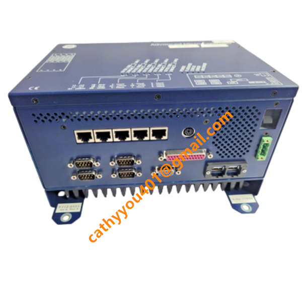
Ethernet Ports: 5 integrated Ethernet interfaces for TCP/IP communication and network interconnection;
Serial Ports: 4 × RS-232 physical ports, 3 of which are available for user application communication;
Serial Expansion: supports 2 × Serial16+ expansion modules, each module offering 16 independent serial channels to expand field device connectivity;
USB Interface: 2 USB ports fitted with Yamaichi locking connectors to prevent accidental disconnection under vibration;
Expansion Slots: 4 × PMC/PC104+ expansion slots, compatible with FIP, Profibus Master/Slave, general fieldbus and fibre-optic Ethernet communication cards;
Feedback Interfaces: built-in encoder pulse input and analog signal acquisition channels for motor speed and process signal closed-loop control;
Protection Functions: integrated over-temperature protection, signal fault detection, communication watchdog for automatic fault response;
Protection Class: IP20 rating, designed for cabinet-mounted installation;
Shock Resistance: withstands 15 g shock load complying with IEC1131 standard for rugged industrial environments;
Application Scenarios: heavy-duty drive control, marine propulsion systems and other demanding industrial control applications;
Communication Protocol Support: Profibus DP, Modbus TCP, FOCS and other mainstream industrial communication protocols.

GE P112-6053 AMC2 Embedded Controller Installation Steps
Pre-installation preparation: Isolate and power down the entire control cabinet. Wear an anti-static wrist strap for ESD protection. Examine the controller for physical defects and confirm that all accessories and PMC/PC104+ expansion modules are available.
Cabinet mounting: Position the controller on the cabinet DIN rail or fixed mounting bracket. Fasten the unit with mounting screws to guarantee reliable anti-vibration installation.
Expansion module assembly (optional): Install PMC/PC104+ fieldbus modules sequentially into the 4 expansion slots. Engage module locking latches to prevent intermittent contact caused by vibration.
Wiring connection: Terminate the 24V DC power cable to the power terminals. Separate communication cables from high-power wiring to minimize electromagnetic interference. Connect RS-232 serial cables, Ethernet cables, encoder feedback lines and analog signal cables to their respective ports. Secure Yamaichi-locked USB connectors after cable insertion.
Cable inspection: Recheck tightness of all wiring terminals. Ensure power terminals have no short circuit or reverse polarity. Confirm every communication and feedback cable is wired to the correct interface.
Pre-power test: Ensure cabinet covers and doors are properly installed. Clear any loose wires or debris inside the cabinet.
Power-on and commissioning: Apply 24V DC power supply. Monitor LED status indicators on the controller. Load firmware and user application software, then configure network settings, fieldbus communication and closed-loop control parameters.
Functional verification: Execute communication tests over Ethernet, Profibus and serial interfaces. Verify acquisition of encoder and analog feedback signals. Confirm watchdog and fault protection features operate normally.
Final handover: Back up all configuration files. Organize and bundle internal cables with cable ties. Complete commissioning documentation prior to commissioning the controller for live operation.

DS200TDAH1BHD
DS200TCRAG1ACC
DS200DTRAG1AAA
DS200DTBBG1ABB
DS200SDCCG4AFD
DS200TCDAG1BDB
IS220PTURH1B
C60G01HCHF8FH6PM8FP6PU6PWXX
DS200TCQCG1BHF



.jpg)