





.jpg)
.jpg)
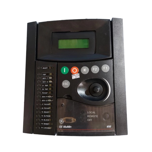







Description
-
BrandGE
-
ModelF650-B-F-J-F1-G1-HI-6H-E
-
Product NameDigital Feeder Protection Relay / Bay Controller
-
Place of OriginCanada
-
Customs HS Code85371011
-
Power Supply110‑250 VDC, 100‑240 VAC
-
Dimensions222 mm × 177 mm × 240 mm
-
Weight4.95 kg
-
Operating Temperature‑40 °C to +85 °C
-
Storage Temperature‑60°C to +85 °C
-
Warranty12 month
-
Product Statusnew
Key Functions of GE F650-B-F-J-F1-G1-HI-6H-E (F650 Feeder Protection Relay)
Delivers full-range feeder protection covering phase overcurrent, ground overcurrent, instantaneous and time-delayed overcurrent, negative-sequence overcurrent, as well as thermal overload protection.
It offers voltage-dependent protection functions including overvoltage, undervoltage, voltage unbalance, loss-of-potential detection and V/Hz protection.
Directional overcurrent protection is available for loop networks and parallel feeder circuits, with configurable directional elements for both phase-to-phase and ground faults.
Integrated breaker management and monitoring features comprise breaker trip-close control, breaker failure protection, breaker wear tracking and trip-circuit supervision.
Automatic reclosing function supports adjustable reclosing counts, dead-time and lock-out logic to restore service after transient faults.
Synchrophasor measurement is embedded to support real-time power system monitoring and wide-area grid analysis.
Powerful metering functions measure three-phase current and voltage, active and reactive power, power factor, frequency, energy and demand values.
Millisecond-accurate Sequence-of-Events (SOE) recorder, fault event logger and oscillography capture fault waveforms to support post-incident root-cause investigation.
Fully configurable digital inputs and relay outputs adapt to on-site interlock, alarm and trip-logic requirements.
Multiple standard communication protocols are supported: Modbus RTU, Modbus TCP, DNP3 and IEC 61850, facilitating smooth integration with SCADA and DCS platforms.
Advanced built-in logic such as cold-load pickup, load encroachment and fuse-failure detection prevents undesired nuisance tripping.
Setting-group switching enables flexible protection-setting adjustment under varied system operating conditions.
Built-in self-diagnostics continuously supervise hardware, power supply and internal circuits and raise alarms when internal anomalies are detected.
This relay is designed for protection, control and metering applications for medium-voltage feeders, distribution substations and industrial power-distribution systems.

Configuration Procedure for Directional Element of GE F650-B-F-J-F1-G1-HI-6H-E
Pre-Configuration Preparation
Verify CT and VT wiring polarity strictly complies with design drawings. Keep CT primary polarity marked toward the busbar, and ensure VT secondary phase sequence matches the relay internal ABC or ACB setting to avoid directional element reverse action or operation failure.
Install EnerVista 650 Setup software and establish communication with the F650 relay through front RS232 or Ethernet port. Read and back up the original configuration file before any modification.
Clarify on-site operation scenarios, define forward direction (fault on feeder side) and reverse direction (fault on busbar side), and select applicable directional elements including 67P phase directional, 67N/67G neutral ground directional or 67SG sensitive ground directional protection.
Step 1: Global Directional Element Parameter Configuration
Navigation Path: Setpoint → Protection Elements → Directional Elements
Enable or disable the directional element and set the operating direction to Forward or Reverse.
Configure the maximum sensitivity characteristic angle within the range of -90° to +90°. Standard settings: -45° for overhead lines and -30° for cable feeders, matching actual system fault impedance angle.
Select polarization mode: cross-phase residual voltage polarization (VBC/VCA/VAB) for 67P phase directional protection; zero-sequence voltage polarization, zero-sequence current polarization or dual polarization for 67G/67N ground directional protection.
Set the polarization voltage threshold (typically 5–10 V secondary) to ensure reliable direction judgment and prevent malfunction during voltage loss.
Configure block logic: select Permission to allow overcurrent tripping when polarization voltage is lost; select Block to lock overcurrent protection and avoid incorrect operation.
Step 2: Bind Directional Supervision with Overcurrent Protection
Navigation Path: Setpoint → Protection Elements → Overcurrent (50/51PH-PL-N-G)
Enable directional supervision function for all overcurrent stages including high instantaneous, low instantaneous and time-delayed overcurrent.
Bind corresponding directional operands: 67P for phase overcurrent protection, 67G/67N for ground overcurrent protection.
Complete binding configuration to enable the directional element to control trip output; otherwise, the directional element only calculates fault direction without protection control capability.

Step 3: System Phase Sequence and Signal Calibration
Navigation Path: Setpoint → Relay Configuration → System Setup
Confirm VT phase sequence (ABC/ACB) is consistent with field wiring to prevent directional logic disorder.
Verify CT/VT ratio parameters to ensure the relay secondary setting matches actual transformer parameters.
Enable load encroachment function for heavy-load feeders, and configure load angle and boundary range to prevent maloperation under high load conditions.
Step 4: Download Configuration and Verify Real-Time Status
Download the validated full configuration to the F650 relay, confirm setting validity, and clear historical alarms and event logs.
Check real-time status via path: Actual → Status → Protection → Directional Element.
Monitor real-time directional flags (Forward Operate / Reverse Operate / Inhibit) under live load.
Check the measured angle between fault current and polarization voltage to confirm consistency with the preset characteristic angle.
Step 5: Secondary Injection Commissioning Test (Primary Equipment De-energized)
Inject forward fault current and matching polarization voltage, confirm the directional element operates normally and the corresponding overcurrent stage enables tripping.
Inject reverse fault electrical signals, verify the directional element blocks trip logic and the relay has no trip output.
Simulate polarization voltage loss fault, check whether the protection action conforms to preset block/permission logic.
Record all test data and results in the commissioning report.
Step 6: Post-Commissioning Backup and Archiving
Export and archive the final configuration file, COMTRADE fault recording template and SOE event settings.
Sort and record key parameters including characteristic angle, polarization mode, operating direction and block logic for future maintenance and inspection.
DS200TDAH1BHD
DS200TCRAG1ACC
DS200DTRAG1AAA
DS200DTBBG1ABB
DS200SDCCG4AFD
DS200TCDAG1BDB
IS220PTURH1B
C60G01HCHF8FH6PM8FP6PU6PWXX
DS200TCQCG1BHF


.jpg)

.jpg)
.jpg)







