





8F5D2D0F17AD46109F18ACEAFBA0082D.jpg)
.jpg)
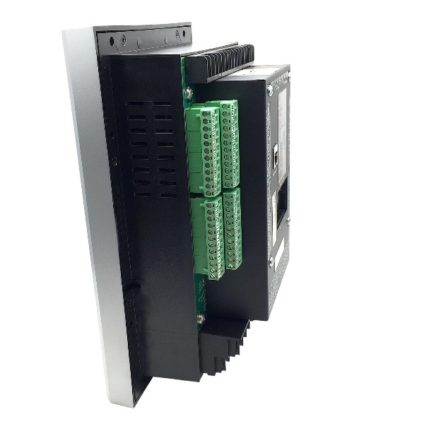







Description
-
BrandGE Multilin
-
Model369-LO-R-0-0-E-0-E
-
Product NameDigital Motor Management Relay
-
Place of OriginCanada
-
Customs HS Code85362000
-
Power Supply20‑60 VDC or 20‑48 VAC
-
Dimensions296mm × 107mm × 205mm
-
Weight4.5kg
-
Operating Temperature‑20℃ to +65℃
-
Storage Temperature‑40℃ to +85℃
-
Warranty1 year
-
Product Statusnew brand
Practical Application Cases for GE Multilin 369-LO-R-0-0-E-0-E Motor Management Relay
The GE Multilin 369-LO-R-0-0-E-0-E is a versatile motor management relay for medium-voltage three-phase induction motors. It integrates comprehensive protective functions, high-precision metering, RTD temperature monitoring, fault event recording and Modbus-RTU communication, widely adopted in power, water treatment, mining and petrochemical industries. The following presents optimized, practical field application cases.
Case 1: 4.16kV Circulating Water Pump Motor – Thermal Power Plant
Site Background
The thermal power plant is equipped with two sets of 4.16 kV, 1250 HP circulating water pump motors for unit cooling systems. These motors operate continuously around the clock; accidental tripping will cause cooling system breakdown, resulting in unit load reduction or full shutdown. The original electromechanical relays only provided basic overcurrent protection, lacking thermal overload modeling, real-time temperature monitoring and fault recording functions. The 369-LO-R-0-0-E-0-E relay was deployed for full system upgrade.
Hardware Configuration
5 A secondary CT input, matched with core balance CT for high-sensitivity 50G ground fault protection
6-channel RTD wiring for real-time monitoring of motor stator winding and front/rear bearing temperature
Modbus-RTU communication interface for data interconnection with plant DCS system
Digital inputs for circuit breaker status and external reset signals; configurable trip and alarm output relays interlocked with breaker trip coils and on-site alarm annunciators
Key Parameter Configuration
49 thermal overload protection calibrated in accordance with motor thermal time constant
50 instantaneous overcurrent protection for short-circuit faults and 51 time-delayed overcurrent as backup protection
46 current unbalance protection for phase loss and three-phase imbalance detection
Customizable RTD overtemperature alarm and trip thresholds
Repeat start inhibition function to prevent frequent motor startup damage

On-Site Operation Effects
Real-time operating data including three-phase current, equipment temperature, start/stop counts and thermal capacity usage is uploaded to the DCS monitoring platform for centralized supervision.
When poor contact in the high-voltage cabinet caused phase loss, the 46 unbalance protection triggered an early pre-alarm. Maintenance personnel eliminated potential faults in advance without unplanned downtime.
Built-in event logs and oscillography records capture complete fault waveforms and event sequences after tripping, cutting fault diagnosis time from several hours to 15–30 minutes.
Effectively prevents motor winding burnout caused by frequent restart after transient power disturbances.
Case 2: 3.3kV Raw Water Feed Pump – Municipal Wastewater Treatment Plant
Site Background
The 3.3 kV, 800 HP raw water feed pump serves the sewage treatment process. Its operating load fluctuates with water level changes, and the impeller is prone to jamming by foreign matter. Meanwhile, the high-inertia pump may reverse during coast-down. The original protection device cannot identify reverse rotation status, and restarting under reverse rotation once caused severe coupling mechanical damage.
Hardware Configuration
369-LO-R-0-0-E-0-E relay installed inside medium-voltage switchgear
Proximity speed sensor connected to relay digital input for motor residual speed monitoring
Phase current CT and zero-sequence CT configured for overcurrent and ground fault protection
Local HMI for on-site inspection; alarm signals transmitted to plant PLC control system
Core Applied Functions
Reverse rotation start blocking: The relay monitors residual speed during motor coast-down and locks startup commands until the speed drops below 12% of synchronous speed, eliminating mechanical impact damage from reverse startup.
Stall and locked-rotor protection to identify impeller blockage caused by foreign debris.
Adaptive thermal protection that accumulates heat based on actual variable load conditions to avoid misoperation and missing protection.
On-Site Operation Effects
Completely eliminates mechanical coupling damage caused by reverse rotation restart.
The stall early warning function successfully triggered twice during foreign matter blockage, enabling timely equipment isolation and avoiding motor winding burnout faults.
Case 3: 4kV Conveyor Drive Motor – Mineral Processing Plant
Site Background
The 4 kV, 1500 HP belt conveyor drive motor operates in a dusty, harsh mining environment. It features large starting inertia, frequent heavy-load startup and severe mechanical impact, facing multiple risks including startup locked rotor, three-phase current unbalance and insulation aging ground faults.
Configuration & Applied Functions
Full electrical protection suite: 50/51 overcurrent, 49 thermal overload, 46 current unbalance, 50G ground fault and phase reversal protection.
Startup supervision: Monitors motor acceleration time and trips when the startup duration exceeds the allowable locked-rotor time.
Startup frequency counting and repeat start inhibition to limit illegal frequent jogging operation.
Automatic recording of startup duration, peak starting current and trip causes for each operation.
Practical Benefits
The maintenance team analyzes historical startup current data to assess motor operating health and predict potential risks.
Long-term ground fault residual current trend analysis identifies gradual insulation aging, supporting predictive overhaul and avoiding sudden catastrophic motor failure.
Case 4: 3kV Agitator Motor – Petrochemical Refinery
Site Background
The 3 kV, 630 HP reactor agitator motor runs continuously for petrochemical reaction processes. The medium viscosity changes with reaction temperature, resulting in variable motor load. Motor failure will cause full process shutdown and huge economic losses, requiring ultra-high operational stability.
Deployment & Core Functions
Multi-channel RTD monitoring for stator winding and dual-end bearing temperature.
Temperature-compensated thermal overload model improves protection accuracy under long-term light overload conditions.
Undercurrent alarm function to identify shaft fracture and coupling failure when the motor runs no-load with stalled process equipment.
Modbus-RTU uploads all operating and status data to the petrochemical DCS for unified asset management.
Typical Fault Handling Application
When increased medium viscosity caused gradual motor overload, the relay issued a thermal capacity pre-alarm in advance. Operators adjusted process parameters timely to avoid thermal overload tripping.
The undercurrent alarm accurately detected agitator shaft fracture, enabling rapid maintenance and preventing secondary production accidents.
Summarized On-Site Application Experience
1. The 49 thermal overload protection must be set strictly according to motor nameplate thermal time constants; RTD temperature compensation significantly improves protection accuracy for variable and light-load operation.
2. Repeat start inhibition and reverse rotation blocking are essential safety functions for high-inertia equipment (pumps, fans, conveyors), and incorrect configuration will lead to mechanical damage.
3. Make full use of the relay’s built-in event recorder and oscillography function; always download fault records for accurate root cause analysis after tripping.
4. Modbus-RTU wiring must comply with polarity specifications; ground potential difference and electromagnetic interference are the main causes of communication anomalies.
5. Complete parameter backup via EnerVista software is mandatory before relay replacement, maintenance or firmware upgrade.
6. This relay only supports Modbus-RTU (RS485) communication with no Ethernet interface.
Practical Application Limitations
1. Designed exclusively for medium-voltage induction motors, not applicable to low-voltage small motors without CT transformation.
2. No direct high-voltage input port; external PT configuration is required if overvoltage/undervoltage protection is needed.
3. This 369-LO-R-0-0-E-0-E model does not support 87M motor differential protection.

Fault-Diagnosis Procedures for GE Multilin 369-LO-R-0-0-E-0-E Motor Management Relay
General Diagnostic Workflow
Inspect front-panel LED indicators and display content to capture active trip and alarm information.
Navigate to `Actual → Event Log` either via the local front-panel keypad or EnerVista configuration software, to retrieve time-stamped protective-element triggers, measured process values and the complete sequence-of-events record.
Download disturbance oscillography files to conduct in-depth analysis for transient intermittent faults.
Classify root causes into actual motor failures, wiring/CT-PT installation defects, incorrect parameter settings, and internal relay hardware self-test faults.
Only reset the trip latch after the underlying fault has been fully resolved. Reset operations can be completed by pressing the front-panel RESET button, triggering the external reset dry-contact, or issuing a remote software reset command. Reset commands will be rejected if fault conditions still persist.
Self-Test Fault Diagnosis (Relay Hardware Malfunction)
Symptoms: "SELF-TEST FAIL" warning message, hardware fault alert, blank display screen, unresponsive keypad operation.
Troubleshooting steps:
Verify auxiliary control power supply; measure input voltage at power terminals against rated range: 85-265 VAC / 88-300 VDC.
Execute a complete power-cycle: cut off auxiliary power supply for 3-5 minutes, then restore power to the relay.
Extract internal self-test error logs using EnerVista. Typical failure codes include RAM malfunction, ROM checksum mismatch, and analog signal circuit anomalies.
Check rear terminal block tightness and ensure the relay module is fully seated within its housing. If self-test faults remain after power-cycling, hardware damage is confirmed and the relay unit shall be replaced.
Typical Protection-Element Fault Diagnosis
49 Thermal Overload Trip (Thermal Model Protection Trip)
Probable causes: continuous motor overload, excessively frequent motor starting cycles, insufficient cooling interval between startups, improperly configured thermal-curve parameters.
Diagnosis method: Monitor real-time TCU (Thermal Capacity Used) readings. Check actual motor operating load, startup frequency, and verify whether the motor cooling-time constant matches nameplate specifications. Allow adequate cooling duration before attempting motor restart.
50 Instantaneous Overcurrent / 51 Time-Overcurrent Trip
-50 Trip: Indicates high-magnitude short-circuit fault. Perform inspection for short-circuit damage on motor windings, power supply cables, and switching contactor assemblies.
-51 Trip: Points to sustained overload or moderate-level system faults. Compare fault current values recorded in event logs with relay pickup thresholds. Confirm CT wiring integrity and ensure programmed CT ratio matches physical current-transformer hardware.
46 Negative-Sequence / Current-Unbalance Trip
Root causes: single-phase loss, blown fuse, severe three-phase load imbalance, CT secondary open-circuit or incorrect wiring connections.
Diagnosis: Measure three-phase actual operating current; inspect CT secondary circuit for open-circuit hazards; validate that three-phase current deviation stays within acceptable limits.
Ground Fault Trip (50G / 51G)
Inspect continuity and integrity of ground-CT wiring; test motor winding insulation resistance and power-cable sheath insulation performance. Confirm ground-fault pickup setting is compatible with the site earthing configuration.
Mechanical Jam / Stall Trip
Probable causes: mechanical blockage of driven equipment, excessive starting load, or insufficient acceleration-time parameter setting.
Diagnosis: Review starting-current profiles and acceleration-duration data stored within start-history logs. Examine mechanical transmission components; adjust stall-detection parameters only when permitted by actual mechanical characteristics.
RSI Repeat-Start Inhibit Alarm / Spurious Trip
Symptoms: The relay prevents motor restart with no evident hardware fault; trip LED remains falsely latched.
Root cause: Repeat-start-inhibit logic is incorrectly assigned to the main trip output matrix.
Corrective action: Modify output-matrix configuration; remap the RSI function to an auxiliary alarm output rather than main trip relay. Double-check that the programmed motor thermal time-constant aligns with motor nameplate data.
RTD Temperature-Related Fault
Alarm categories: RTD overtemperature, RTD open-circuit fault, RTD short-circuit fault.
Troubleshooting: Verify continuity of field-installed RTD wiring; measure physical resistance values of RTD sensors; confirm selected RTD type and scaling parameters match on-site sensor hardware.
Communication Fault Diagnosis (Modbus-RTU)
Symptom: No valid data exchange between relay and upper-level host system.
Validate A-B bus wiring polarity, terminating resistor installation, baud-rate setting, parity configuration, and slave-station address consistency between relay and master device.
Check relay response frames for illegal function-code or illegal-address error feedback.
Mitigate electromagnetic interference and ground-potential-difference risks; single-end grounding for shielded communication cable is recommended.
Common External Wiring & Transducer Troubleshooting
CT secondary circuit: Strictly avoid open-circuit operating conditions. Check terminal-wiring tightness; guarantee consistency between physical CT ratio and relay-programmed value.
Digital input channel: Confirm wetting-source voltage (24 VDC / 125 VDC) matches hardware specifications; inspect for contact bounce and loose field contacts.
Trip output loop: Verify trip-circuit continuity; check correct wiring status for circuit-breaker auxiliary feedback signals.

DS200TDAH1BHD
DS200TCRAG1ACC
DS200DTRAG1AAA
DS200DTBBG1ABB
DS200SDCCG4AFD
DS200TCDAG1BDB
IS220PTURH1B
C60G01HCHF8FH6PM8FP6PU6PWXX
DS200TCQCG1BHF



.jpg)
.jpg)
.jpg)







