





3D63C75393FD4698B41590BDC07EE7AF.jpg)
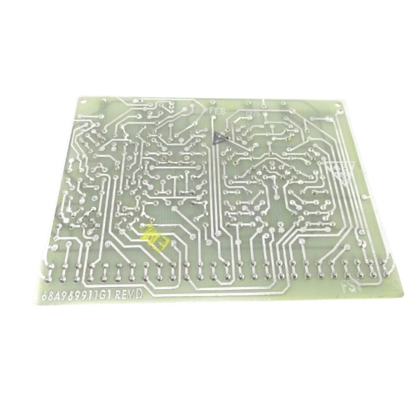







Description
-
BrandGE
-
ModelIC3600SSVG1
-
Product NameServo Valve Drive Circuit Board
-
Place of OriginUnited States
-
Customs HS Code8538900000
-
Power Supply1.35A
-
Dimensions272mm × 215mm × 33mm
-
Weight1.10kg
-
Operating Temperature-20℃ to +70℃
-
Storage Temperature-40℃ to +85℃
-
Warranty12 month
-
Product Statusnew and original
IC3600SSVG1 GE Board Functions
The IC3600SSVG1 functions as a specialized analog signal processing module for GE Mark I and Mark II Speedtronic gas- and steam-turbine control systems.
It accepts multi-channel raw analog field signals from on-site sensors and executes signal scaling, noise filtering and level translation, converting unconditioned sensor inputs into standardized internal signals usable by the turbine controller.
It generates well-regulated buffered analog outputs to feed back critical turbine process parameters such as temperature, pressure and flow for system monitoring purposes.
Built-in galvanic separation between field circuits and control logic minimizes electrical noise, voltage surges and inductive disturbances, offering effective protection for vital main-control hardware.
The board carries out real-time signal sampling for turbine closed-loop adjustment and safety-monitoring circuits, and transmits conditioned measurement values to main logic circuit boards.
Configuration is completed through on-board hardware jumpers to match input signal ranges with various field sensor types; no independent application software is needed.
As a vital analog interface unit, it guarantees dependable transfer of process variables, underpinning turbine speed governing, load regulation and safety interlock protection operations.

IC3600SSVG1 GE Servo Valve Drive Board Wiring Instructions
Backplane Connection: Install the module into its assigned slot inside the GE Mark I / Mark II Speedtronic rack. The edge-finger connector realizes power supply delivery and internal signal communication with the system backplane. 24 VDC working power and logic bus signals are supplied through backplane pins, so no independent external power wiring is needed for this board.
Field Servo Valve Wiring: Link servo-valve drive output terminals to the matching solenoid coil terminals of on-site servo valves. Polarity must be strictly followed; reversed positive-negative connections will result in faulty valve operation or permanent module damage. Shielded twisted-pair cables are required for servo-valve circuits. Cable shields shall be single-point grounded to the protective ground of the control rack, while the field-end shield remains ungrounded to mitigate electromagnetic interference.
Analog Feedback Signal Wiring: Run position feedback signals coming from servo valves or actuators to the analog input terminals of IC3600SSVG1. Ensure positive and negative signal terminals are correctly paired. Adhere to channel-specific terminal definitions when connecting RTD or voltage-mode feedback sensors. All low-level feedback signal circuits must adopt shielded twisted-pair cables.
Internal System Signal Wiring: Processed control signals are exchanged with other main-logic boards over the rack backplane, eliminating the need for additional external inter-board wires. Before starting wiring work, set on-board jumpers properly to adapt to servo-valve coil impedance, input signal range and actual control mode.
Ground Wiring: Connect the rack protective ground terminal to the plant safety grounding system. Keep signal ground isolated from high-power equipment ground to prevent ground-loop interference triggered by multi-point grounding arrangements.
Pre-power-on Wiring Inspection: Make sure all field cables are securely crimped with no stray loose wire strands. Check for short-circuit faults between drive outputs, feedback signals and ground. Reconfirm servo-valve wiring polarity and jumper configuration consistency prior to power application.
Wiring Precautions: Maintain physical separation between high-power servo drive cables and low-level feedback signal cables; do not route them inside one common cable conduit. Perform lock-out-tag-out safety procedures throughout all wiring activities to prevent electric shock hazards and accidental equipment movement. Consult the original GE schematic drawing for precise pin definitions of every channel.

DS200TDAH1BHD
DS200TCRAG1ACC
DS200DTRAG1AAA
DS200DTBBG1ABB
DS200SDCCG4AFD
DS200TCDAG1BDB
IS220PTURH1B
C60G01HCHF8FH6PM8FP6PU6PWXX
DS200TCQCG1BHF


.jpg)

.jpg)

.jpg)







