





59AC0097438445A69F17A03914C8B99F.jpg)
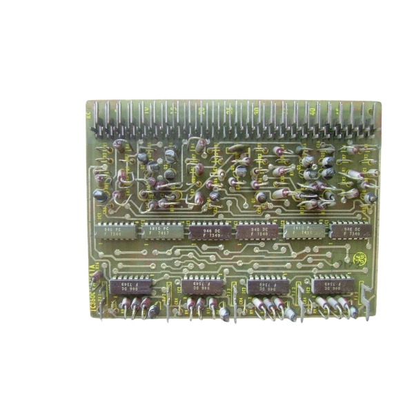







Description
-
BrandGE
-
ModelIC3600LRDJ1
-
Product NameIndustrial Turbine Control Circuit Board
-
Place of OriginUnited States
-
Customs HS Code8538900000
-
Power Supply24V DC
-
Dimensions280mm × 220mm × 35mm
-
Weight1.2kg
-
Operating Temperature-20℃ to +70℃
-
Storage Temperature-40℃ to +85℃
-
Warranty12 month
-
Product Statusnew and original
IC3600LRDJ1 GE Relay Driver Board Key Advantages
High-reliability relay driver board customized for GE Mark I / Mark II Speedtronic gas and steam turbine control systems.
It features superior signal isolation, isolating low-voltage logic circuits from high-power relay and solenoid coils to safeguard core control hardware against voltage surges and inductive interference.
It precisely amplifies feeble logic control signals to actuate external relays, solenoid valves and actuators, supporting reliable turbine safety interlock and trip-loop control.
Adopting heavy-duty industrial-grade circuit design and rigorous factory validation, it maintains consistent stable performance in demanding field operating environments.
It boasts seamless native compatibility with legacy Mark I/Mark II system architecture, supporting plug-and-play replacement without extensive system reconfiguration.
Its compact modular PCB layout simplifies installation, routine inspection and component-level repair, effectively cutting equipment downtime.
It fits diverse turbine application environments, including offshore marine equipment, industrial plants and large-scale power-generating facilities.

IC3600LRDJ1 GE Relay Driver Board Fault Diagnosis Procedure
Safety preparation: Disconnect power supply for the turbine control system and release residual stored energy. Implement lock-out and tag-out procedures prior to board removal and testing to avoid electric hazards and unintended turbine tripping.
Visual inspection: Examine the PCB assembly for burn marks, bulging capacitors, fractured solder joints, corrosion, discoloration and component deterioration. Inspect edge connectors for oxidation, bent pins and loose terminal connections.
Static resistance test (power-off condition): Apply a multimeter to measure continuity of input channels, relay-drive output loops and grounding paths. Detect short-circuits across power rails to ground as well as open-circuit failures on signal traces.
Power supply measurement (power-on condition): Confirm the input operating voltage complies with official rated values. Identify voltage drop, unstable fluctuation and excessive ripple triggered by poor contact or deteriorated power-related components.
Logic input signal test: Feed standard low-voltage logic signals from Mark I / Mark II controller to the board input terminals. Validate that input status shifts strictly follow predefined system logic.
Drive output test: Observe output terminals upon activation of logic input signals. Confirm stable on-off switching of driving signals for relays and solenoids. Measure output voltage and current to identify inadequate driving capacity.
Isolation performance check: Perform insulation testing between low-voltage logic section and high-power output section. Degraded insulation points to isolation circuit breakdown, which may result in signal interference and cross-loop malfunctions.
System function verification: Reinstall the board into the Speedtronic platform and execute simulated interlock and trip-loop tests. Ensure external relays, solenoid valves and actuators operate in accordance with design requirements.
Swap comparison test: Substitute the suspect IC3600LRDJ1 board with a verified functional unit. If symptoms vanish after replacement, the original board is determined faulty.
Fault logging and root-cause analysis: Document fault symptoms, measured readings and site operating conditions. Investigate contributing factors including transient overvoltage, circuit overload, excessive ambient temperature and humidity-induced board damage.

DS200TDAH1BHD
DS200TCRAG1ACC
DS200DTRAG1AAA
DS200DTBBG1ABB
DS200SDCCG4AFD
DS200TCDAG1BDB
IS220PTURH1B
C60G01HCHF8FH6PM8FP6PU6PWXX
DS200TCQCG1BHF


.jpg)
.jpg)
.jpg)







