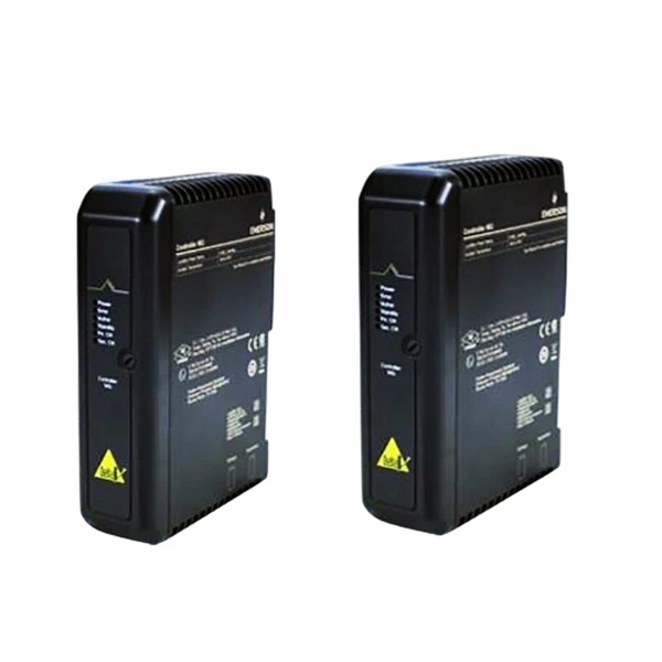







Description
-
BrandEmerson
-
ModelVE5009
-
Product NameDeltaV 24/12-VDC Enhanced System Power Supply
-
Place of OriginUnited States
-
Customs HS Code8504409990
-
Power Supply12 VDC (-4% ~ +5%), 24 VDC (±20%)
-
Dimensions178 mm × 110 mm × 95 mm
-
Weight0.7 kg
-
Operating Temperature-40 °C to 60 °C
-
Storage Temperature-40 °C to 70 °C
-
Warranty12 month
-
Product Statusnew
Emerson VE5009 (KJ1501X1-BC3) Technical Specifications
Alternative Part Number: KJ1501X1-BC3
Input Ratings
12 VDC input: -4% to +5%, 14.8 A
24 VDC input: ±20%, 6.1 A
Input Protection: Internal non-replaceable fuse; soft-start circuit for inrush current limiting
Output Ratings
12 VDC output: 10 A maximum under 12 VDC input, 6 A maximum under 24 VDC input
3.4 VDC output: 2.0 A maximum
Overvoltage Protection: Output shuts down when voltage reaches 110% to 120% of nominal value
Isolation: Galvanic isolation provided between system power and field power circuits
Environmental Specifications
Relative Humidity: 5% to 95%, non-condensing
Vibration: 1 mm peak-to-peak from 5 Hz to 16 Hz; 0.5 g from 16 Hz to 150 Hz
Shock: 10 g, ½-sine wave, 11 ms duration
Airborne Contaminants: Meets ISA-S71.04-1985 Class G3
Mounting & Compatibility
Engineered for DeltaV M-series carrier slots
Supplies power to DeltaV controller and I/O backplane
Removes the need for standalone 24 V to 12 V bulk power conversion modules
Certifications: CE, UL
Power Connection: 2-wire DC primary power interface

Emerson VE5009 Enhanced System Power Supply Detailed Installation Guide
Pre-Installation Preparation and Safety
Implement lockout-tagout procedures and completely de-energize the DeltaV M-series carrier and all bulk power supplies prior to installation. Wear an anti-static wrist strap to protect electronic components from electrostatic discharge. Confirm the module part number is VE5009 (KJ1501X1-BC3) and verify compatibility with the DeltaV M-series power and controller carrier. Prepare appropriate copper conductors and a calibrated torque screwdriver. Inspect the module, carrier backplane and connector pins for physical damage, contamination or bent contacts. Ensure the installation site meets humidity, vibration and airborne contaminant criteria defined by ISA-S71.04-1985 Class G3.
Mechanical Module Mounting
The VE5009 is intended for installation within M-series carrier power slots. Align the module edge connectors with the carrier card guides. Slide the module horizontally into the assigned power slot until it fully mates with the backplane. Engage the top and bottom locking latches to fix the module in place. Never apply excessive force during insertion; halt the operation and recheck alignment if significant resistance is encountered. This power module supplies the controller and I/O backplane via the carrier’s internal power bus, and no additional external wiring is required for backplane power distribution.
Chassis Grounding
Run a short, heavy-gauge copper conductor between the module chassis grounding terminal and the low-impedance system instrument ground bus. Tighten the ground termination reliably. Correct grounding stabilizes signal reference potential, suppresses electrical noise and assists the internal overvoltage protection circuitry. Adopt a unified system grounding architecture to prevent ground loops.
DC Input Power Wiring
The VE5009 supports 2-wire bulk DC input at either 12 VDC or 24 VDC. Select an input power source that falls within the module’s rated operating range. Strip insulation to a suitable length, insert conductors into the bulk power connector, and ensure no bare copper strands extend outside the terminals. Tighten terminals to the specified torque value. Separate DC power cables from high-voltage AC cables to minimize transient interference and electromagnetic noise. Route analog and communication cables apart from bulk power wiring.
Pre-Power-On Inspection
Reconfirm the module is fully seated and latched inside the carrier slot. Check that the ground connection is secure and the DC input polarity is correct. Inspect bulk power wiring for short circuits, loose wire strands and open circuits. Calculate the total system power draw to confirm the VE5009 output capacity can sustain the downstream controller and I/O load. Verify cable segregation complies with routing requirements.
Power-Up and Functional Verification
Re-energize the bulk DC supply incrementally. Monitor the front-panel power status LED. A steady illuminated indicator shows the module has completed self-test and is delivering power to the backplane. Access DeltaV system software to confirm normal detection of the carrier, controller and I/O modules. Watch for overvoltage, overcurrent and module fault alarms. If faults appear, cut off power and recheck module seating, grounding and input wiring.
Hot-Swap and Replacement Notes
The VE5009 supports hot swapping within certified DeltaV M-series systems. Disconnect bulk input power before extracting the module. Release the locking latches and pull the module straight out of the carrier. Install the replacement module following the same alignment and latching procedure. This device is fitted with an internal non-replaceable fuse; disassembly is prohibited. The complete module must be replaced once internal protection activates.
Post-Installation Maintenance
Maintain unobstructed airflow around the module and clear ventilation paths of debris. Periodically check connector terminals for torque loss and retighten when necessary. Do not alter internal circuitry. Keep spare modules stored inside static-protective packaging. Document the module location, input voltage type and system load information for later maintenance activities.

SE4035S2B1 KJ3221X1-BK1
CE4022
VE3008
1C31194G03
AMS-2140
FloBoss S600+
5X00875G01
SE5109
SE3051C0
A6500-UM


.jpg)