




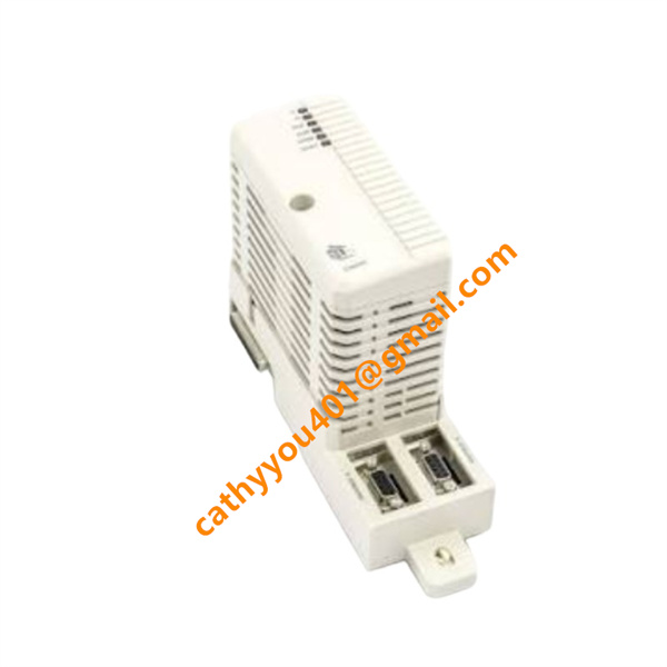
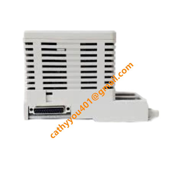







Description
-
BrandABB
-
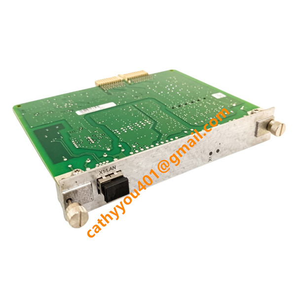
ModelCI854AK01
-
Product NamePROFIBUS DP Communication Interface Module
-
Place of OriginSweden
-
HS Code8517620000
-
Dimensions59 mm × 185 mm × 127.5 mm
-
Weight0.72 kg
-
Operating Temperature-20 ℃ ~ +60 ℃
-
Storage Temperature-40 ℃ ~ +85 ℃
-
Part Number3BSE030220R1
-
Warranty12 month
-
Product StatusNew and original
ABB CI854AK01 3BSE030220R1 Introduction & Technical Specifications
Core Product Advantages
1. Standard PROFIBUS DP Master Function: Fully compliant with international PROFIBUS DP standard, highly compatible with mainstream brand PROFIBUS slave devices in the market.
2. Hot-swappable Structure: Module can be replaced online during system running without rack power-off, minimizing maintenance downtime and production loss.
3. Complete Status Diagnosis: Front panel LED indicators display power status, running state, bus fault and communication link error, supporting quick on-site fault location.
4. Strong Environmental Adaptability: Conformal coated circuit board, excellent anti-vibration and anti-electromagnetic interference performance, suitable for heavy industrial workshops.
5. High Bus Load Capacity: Supports up to 99 slave nodes, meeting large-scale field equipment networking requirements for complex production lines.
6. Perfect Software Compatibility: Configurable, programmed and diagnosed entirely via ABB Control Builder M software without additional driver development.
7. Compact Rack Layout: Narrow single-slot design saves cabinet space, allowing high-density arrangement of multiple communication modules in one control rack.

CI854AK01 3BSE030220R1 ABB Step-by-Step Wiring and Installation Method
Step 1: Pre-installation safety preparation
Cut off the main power supply of the AC 800M control rack completely and release residual voltage. Inspect CI854AK01 module and TP854 baseplate for physical damage, pin deformation or burnt components. Complete protective earthing of the control cabinet according to IEC electrical standards and prepare PROFIBUS shielded twisted-pair cables.
Step 2: Mechanical installation into rack
Insert the TP854 baseplate into an empty communication slot on the rack backplane, tighten fixing screws on both sides to fix the baseplate firmly. Insert the CI854AK01 main module vertically into the baseplate until fully connected with backplane connector, then lock the front panel rotary buckle to prevent loosening caused by equipment vibration.
Step 3: Internal power and backplane connection
Power supply and internal CEX-Bus data transmission between the module and main controller are automatically completed through the rack backplane. No extra external 24 VDC power wiring is required.
Step 4: PROFIBUS DP field bus wiring
1. Use standard PROFIBUS shielded cable, connect line A and line B to corresponding pins of the 9-pin D-sub connector strictly following polarity;
2. For the first and last devices on the entire PROFIBUS bus trunk, activate the built-in terminal resistor to eliminate signal reflection;
3. Route PROFIBUS signal cables separately from high-power AC cables to avoid crosstalk interference; implement single-end shielding grounding at the control cabinet side.
Step 5: Earthing reinforcement
Connect the grounding terminal of the TP854 baseplate to the cabinet PE protective earth wire with copper wire to enhance EMC anti-interference performance.
Step 6: Inspection and power-on commissioning
Double-check module locking tightness, cable connection reliability, terminal resistor setting and grounding condition. Restore rack power supply and observe front LEDs: steady green POWER and RUN lights indicate normal operation; red FAULT light lights up for bus short circuit, disconnection or communication failure. Download hardware configuration and PROFIBUS parameter settings via Control Builder M, conduct cyclic data test between controller and field slave devices to finish commissioning.