





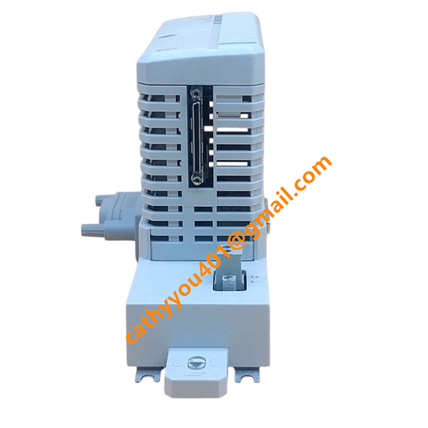

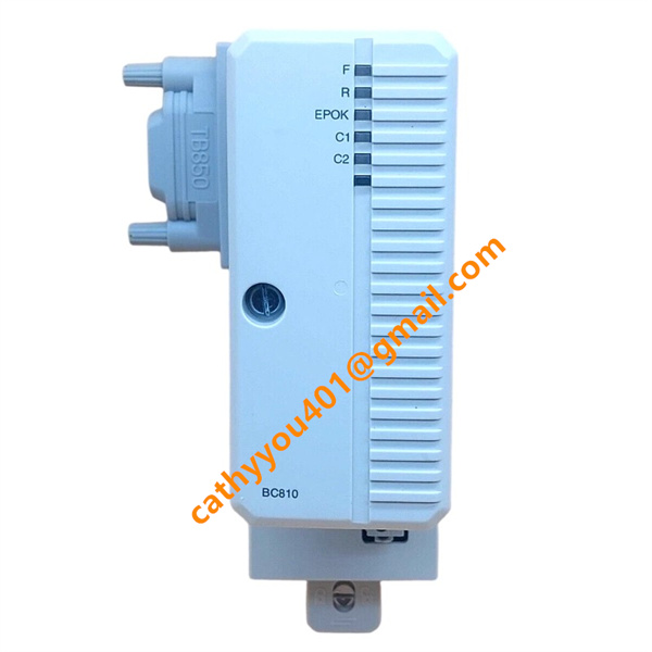







Description
-
BrandABB
-
ModelBC810K01
-
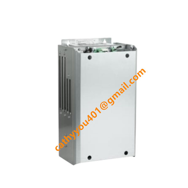
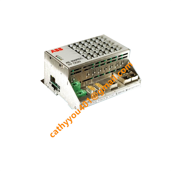
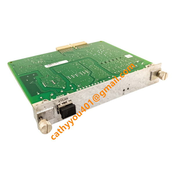
Product NameCEX-Bus Interconnection Unit
-
Place of OriginSweden
-
HS Code8538909999
-
Dimensions59 mm × 185 mm × 127.5 mm
-
Weight0.77 kg
-
Operating Temperature0 ℃ ~ +60 ℃
-
Storage Temperature-40 ℃ ~ +85 ℃
-
Part Number3BSE031154R1
-
Warranty12 month
-
Product StatusNew and original
ABB BC810K01 3BSE031154R1 Product Introduction & Technical Specifications
Core Product Advantages
1. High-Speed Backplane Data Transmission: Optimized CEX-Bus hardware design delivers low-latency synchronous data interaction between rack modules, avoiding communication delay during logic operation and real-time signal acquisition.
2. Hot-Swap Support: The interconnection unit and matched baseplate support online hot replacement without cutting off the entire system power supply, greatly shortening maintenance downtime and avoiding production halt losses.
3. Flexible System Expansion: Enables convenient cascading of multiple extension racks to expand control scale, perfectly compatible with S800, S600 series remote I/O modules and all AC 800M processor units.
4. Robust Anti-Interference Performance: PCB with conformal coating, built-in surge suppression and ground loop isolation circuits, stable operation in workshop environments with high vibration, dust and electromagnetic radiation.
5. Complete Built-In Self-Diagnosis: Real-time fault detection for bus short circuit, loose backplane contact and overcurrent; front LED indicators directly display fault location for rapid troubleshooting without software debugging.
6. Vibration-Resistant Locking Structure: Front panel mechanical lock fixes the module tightly to the baseplate, preventing poor contact caused by long-term equipment vibration in heavy industry scenarios.
7. Seamless Software Compatibility: Fully configured and diagnosed via ABB Control Builder M programming software, no extra driver development required for system integration.


BC810K01 3BSE031154R1 ABB Standard Step-by-Step Wiring & Installation Method
Step 1: Pre-Installation Safety Preparation
Completely disconnect the main power supply of the AC 800M control rack and discharge residual voltage inside the cabinet. Inspect BC810K01 unit, TP857 baseplate and TB850 terminator for physical damage, cracked PCB or deformed connectors. Complete cabinet protective earthing strictly per IEC industrial electrical specifications.
Step 2: Mechanical Installation into Main Rack
Insert the TP857 baseplate into an empty dedicated CEX-Bus slot on the main rack backplane, fasten side fixing screws to lock the baseplate firmly. Insert the BC810 main module vertically into the TP857 baseplate until the backplane connector is fully engaged, then twist the front panel lock knob clockwise to secure the module against vibration loosening.
Step 3: Internal Backplane Power Connection
Power supply and internal data communication between BC810K01 and the main controller are automatically realized through the rack CEX-Bus backplane. No additional external 24VDC power wiring is needed.
Step 4: Inter-Rack Expansion Cable Wiring (If Needed)
1. Locate the CEX-Bus OUT port on the main rack BC810 module and IN port on the extension rack BC810 module;
2. Use dedicated shielded CEX-Bus cable to connect OUT terminal of the upper rack to IN terminal of the next extension rack in series cascading mode;
3. Install the TB850 bus terminator at the final end of the entire CEX-Bus line to eliminate signal reflection and guarantee bus integrity.
Step 5: Grounding and Cable Layout Optimization
Route CEX-Bus expansion cables separately from high-current AC power cables to reduce crosstalk interference. Connect the dedicated grounding stud of each baseplate to the cabinet PE protective earth wire with copper conductors for EMC enhancement.
Step 6: Circuit Inspection & Power-On Commissioning
Recheck all module locking status, cable plug tightness, bus terminal installation and grounding continuity. Restore rack main power supply and observe front panel LEDs: steady green POWER and RUN lights represent normal working status; red FAULT light triggers for bus communication failure or hardware abnormality. Complete rack topology configuration via Control Builder M software and test data communication between main rack and extension racks to finish commissioning.