





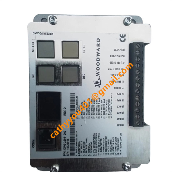







Description
-
BrandWoodward
-
ModelDPG-2201-002
-
Product NameAPECS Digital Speed Governor Controller for Generator Sets
-
Place of OriginUnited States
-
HS Code8537109090
-
Dimensions145mm×98mm×62mm
-
Weight341 grams (12 oz)
-
Operating Temperature-40 °C to +85 °C
-
Storage Temperature-45 °C to +90 °C
-
Power Supply24VDC
-
Warranty12 month
-
Product StatusNew and original
DPG-2201-002 Electrical Technical Parameters
Input Power Voltage Range: Operates from 9 V DC to 30 V DC, fully compatible with standard 12 V and 24 V battery power systems for generator sets.
Continuous Actuator Output Current: Features a maximum continuous output current of 7 A for stable actuator driving.
Peak Surge Output Current: Supports a 14 A peak surge current, with a maximum sustainable duration of 10 seconds to accommodate transient operating conditions.
Minimum Magnetic Pickup Input Signal: Capable of recognizing a minimum 2.0 V AC RMS input signal during engine cranking operation to ensure reliable speed signal acquisition.
Rated Power Consumption: Maximum power consumption of 5 W under nominal operating conditions for low-energy operation.
Speed Regulation Accuracy: Delivers a steady-state speed control accuracy of ±0.25% over the full speed range and entire rated operating temperature spectrum.
Communication Interface: Equipped with RS232 and RS422 serial communication ports, enabling data transmission, parameter configuration and device tuning via exclusive Woodward configuration software.

Installation Guidelines of DPG-2201-002
Mounting Type
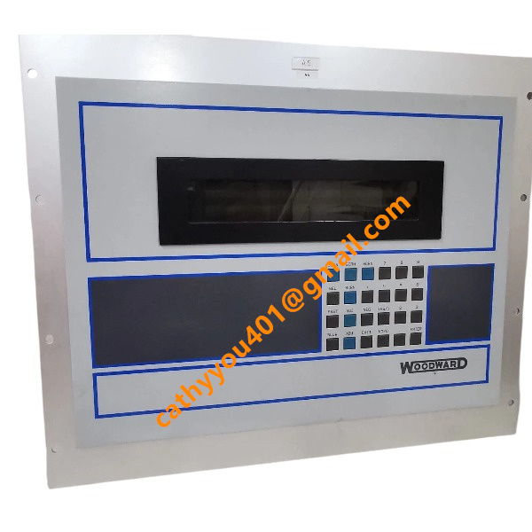
The Woodward DPG-2201-002 is a panel-mounted digital speed governor designed for flush installation on cabinet doors and control panels. It supports direct front operation, parameter checking and on-site troubleshooting, with a compact size and no requirement for DIN rail mounting parts.
Pre-installation Preparation
Select installation locations with adequate heat dissipation, away from severe vibration, high humidity, corrosive gas and strong electromagnetic interference. Cut a standard panel opening per product dimensions and clean the mounting surface to remove debris and burrs. Completely power off the system before installation to ensure operational safety.

Step-by-Step Installation Procedures
Insert the controller through the front of the panel cutout until the front panel fits flush with the cabinet surface. Secure the device with matching rear mounting brackets and fasten the screws evenly to prevent looseness under vibration. Connect power, sensor and communication cables strictly per official wiring diagrams, and tighten all terminals firmly.
Wiring & Installation Specifications
Separate low-voltage signal cables and high-power cables to minimize electromagnetic interference and ensure stable signal collection and device operation. Crimp terminals securely and reserve appropriate cable length to avoid tension damage. Maintain neat and standardized internal wiring for convenient inspection and maintenance.
Dismounting Steps
Fully cut off system power and verify safety before disassembly. Disconnect and mark all power and signal cables. Loosen the rear fixing screws and brackets, then push the controller forward to remove it from the panel cutout.
Installation Environment Restrictions
Reserve sufficient ventilation space for heat dissipation; do not install the unit in fully sealed and poorly ventilated enclosures. The allowable operating ambient temperature ranges from -40 °C to +85 °C, with 5%–95% non-condensing humidity. Avoid long-term exposure to strong vibration and impact environments to protect internal components.