












Description
-
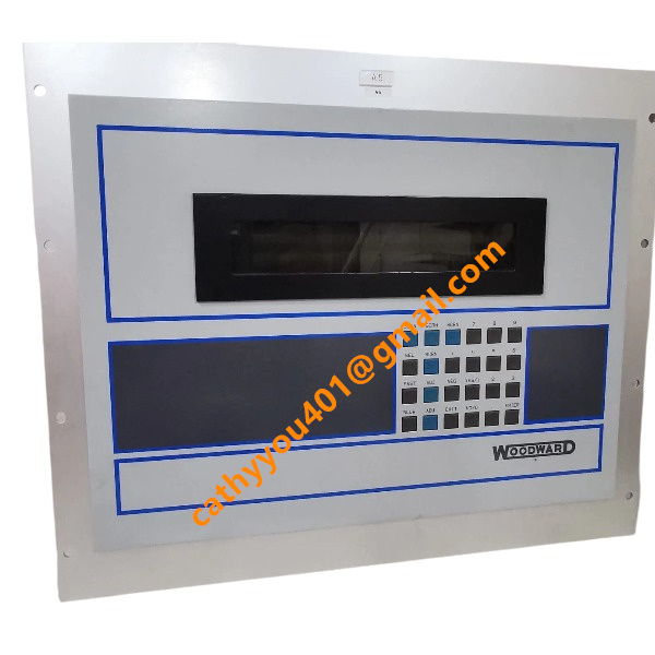
BrandWoodward
-
Model5453-759
-
Product NameMicroNet-Plus 14-Slot Control Chassis
-
Place of OriginUnited States
-
HS Code85372090
-
Dimensions305mm×203mm×152mm
-
Weight1.36 kg (3 lbs)
-
Operating Temperature-40°C to +70°C
-
Storage Temperature-45°C to +85°C
-
Power Supply24VDC
-
Warranty12 month
-
Product StatusNew and original
Woodward 5453-759 Input & Output
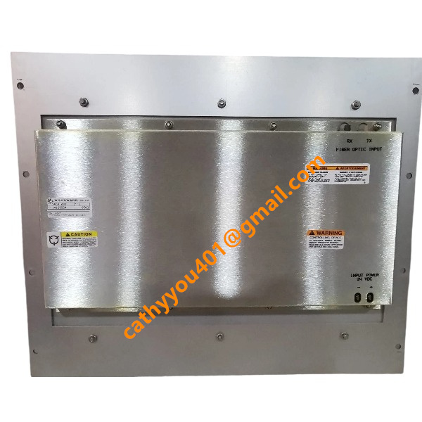
Power Input: Dual redundant 18–36 VDC (nominal 24 VDC); max total load power 320W
Backplane Signal Input Channels: Magnetic pickup speed signals (5–20000Hz), ±10VDC analog voltage, 4–20mA analog current, discrete digital input signals
Backplane Signal Output Channels: Analog drive signals for actuators, digital relay control outputs, bus communication signal routing
Communication Bus Interfaces: Dedicated MicroNet high-speed parallel bus, expansion pins for CAN, RS485 Modbus
Chassis Auxiliary Output: Slot power distribution for all inserted control and I/O modules
Ground Terminal: Protective earth connection for overall EMC shielding
Mounting Method of Woodward 5453-759
Rack Mount Structure
This 14-slot MicroNet-Plus chassis fits vertically inside standard 19-inch industrial cabinets and uses four corner mounting holes for fixation. Operation without a supporting cabinet frame is not supported.
Fixing Steps
Slide the chassis into the designated cabinet tier, align its four mounting holes with cabinet rails, then secure with matching bolts to prevent shifting caused by vibration.
Module Insertion & Locking
Line up plug-in control boards with the backplane connector of each slot, insert the boards completely, and engage metal latches on both sides to maintain reliable pin-to-backplane contact.

Heat Dissipation Clearance
Leave a minimum 40mm empty space above and under the chassis for natural cooling. Keep side ventilation openings unobstructed and avoid mounting heat-producing equipment next to the chassis.
Power & Signal Wiring Rules
Run dual redundant 18–36VDC power wires to chassis power terminals separately from analog, speed feedback and communication cables. Link the chassis grounding terminal to cabinet protective ground for EMC performance. Signal exchange between internal modules relies entirely on the built-in backplane with no extra inter-board wiring required.
Environmental Installation Limits
For indoor use only, with an operating temperature range of -40°C to +70°C. Keep away from locations with high humidity, corrosive vapors, dense dust and persistent severe mechanical shock.
Maintenance Precautions
Cut off all external DC power before installing or removing internal modules to avoid backplane short circuits and pin damage. Every slot has an independent fuse that protects against overload of individual modules.