





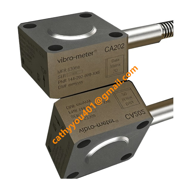
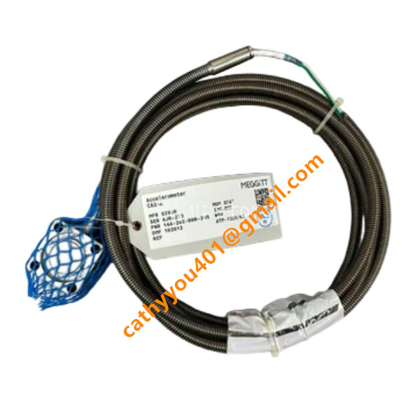







Description
-
BrandVibro Meter
-
ModelCA202
-
Product NameCA202 Piezoelectric Accelerometer
-
Dimensions42 mm × 42 mm × 24 mm
-
Weight250 g
-
Place of OriginSwitzerland
-
HS Code9031809000
-
Operating Temperature-55 ℃ to +260 ℃
-
Storage Temperature-65 ℃ to +365℃
-
Manufacturing part number144-202-000-205
-
Warranty12 month
-
Statusnew and original
Functional Description of Vibro-Meter CA202 (144-202-000-205)
This device is a shear-mode piezoelectric accelerometer with differential charge output. It converts mechanical housing vibration from rotating machinery into a proportional electrical charge signal at 100 pC/g.
Core Functions
Measure absolute housing acceleration vibration of turbines, compressors, generators, pumps and gearboxes within the frequency range of 0.5 Hz-6000 Hz.
Enable continuous long-term vibration monitoring under severe high-temperature industrial environments ranging from -55 °C to +260 °C.
Deliver raw charge signals to external charge amplifiers or signal conditioners such as the IPC704. The conditioning unit converts charge signals into standard voltage or current signals for DCS or vibration protection systems.
Generate valid vibration data for machinery condition diagnosis to identify typical equipment faults, including unbalance, shaft misalignment, loose fasteners and bearing failures.
The hermetically-sealed stainless-steel enclosure paired with a 3-meter integrated armoured cable offers good resistance against mechanical shock, abrasion and environmental pollution, suitable for heavy-duty field applications.
Built-in housing insulation suppresses ground-loop interference and guarantees stable transmission of differential charge signals under on-site industrial wiring conditions.

Operating Instructions for Vibro-Meter CA202 (144-202-000-205)
1. Pre-Installation Inspection
Examine the sensor body and armoured cable for physical defects including dents, cracks and fractured welds.
Confirm permissible operating temperature range: -55 °C to +260 °C. Operation outside this span is prohibited.
Ensure compatibility with supporting charge amplifier or monitoring module, e.g. Vibro-Meter IPC704 or equivalent third-party signal conditioner.
Carry-out insulation resistance test; resistance between signal core and sensor housing must be no less than 100 MΩ.
2. Mechanical Installation
Select measuring positions close to equipment bearing housings. The mounting surface must be flat, thoroughly cleaned and free from paint, rust and grease; surface roughness shall meet N7 or superior standard.
Drill and tap four M6 threaded holes to suit M6×35 mounting bolts.
Install flat washers. Tighten the four bolts evenly to a torque value of 15 N·m. Align the sensor so its sensitive axis stands perpendicular against the mounting plane.
Route the armoured cable with adequate slack. Prevent sharp bends, tensile load, compression and continuous rubbing against metal structures to minimise triboelectric noise. Secure cable runs with clamps; avoid mechanical stress transmitted to the sensor root.
3. Electrical Connection
This unit provides differential charge output and requires no supply voltage. Terminate the free cable conductors to corresponding charge amplifier input terminals strictly in accordance with official wiring diagrams.
Field junction boxes JB105 or JB106 may be adopted for intermediate cable transition where site conditions demand.
Implement housing isolation from equipment ground or comply with project-specified earthing rules to suppress ground-loop interference.
Avoid accidental short-circuit of signal conductors throughout installation and maintenance activities.
4. System Parameter Setup
Configure the charge amplifier sensitivity setting to 100 pC/g, matching the nominal sensor characteristic of CA202.
Define measurement bandwidth from 0.5 Hz to 6000 Hz; ensure critical vibration frequency components of monitored machinery are not filtered out.
Adjust measuring range based on actual equipment vibration magnitude. Continuous peak acceleration shall stay below 400 g, while transient shock peak shall not exceed 1000 g.
Complete end-to-end system calibration prior to commissioning.
5. Commissioning and Normal Operation
Once mechanical assembly and wiring are completed, power-up the signal conditioning hardware.
Lightly tap the sensor casing. A clear vibration reading change on monitoring software indicates intact signal transmission path.
Start-up the machinery and observe real-time vibration amplitude and spectral data. Watch out for unexpected high noise levels or signal drift.
Configure vibration alarm and trip set-points referencing equipment technical documentation and ISO-10816 requirements.
Maintain continuous vibration monitoring during regular plant operation.
6. Fault Diagnosis
No output signal: Check loose connections, cable breakage, incorrect amplifier configuration, short-circuited signal wiring.
Excessive background noise: Check cable friction-induced stress, ground-loop issues, insufficient mounting torque, damaged armoured outer sheath.
Gradual signal drift: Operating temperature out-of-range, degraded insulation performance, loose mounting fasteners.
Shifted sensitivity reading: Past severe mechanical over-shock; perform independent off-site calibration.
7. Critical Safety Precautions
Prevent dropping or heavy impact to the accelerometer. Severe mechanical shock can permanently destroy internal piezoelectric sensing elements.
Standard variant 144-202-000-205 is not suitable for explosive hazardous zones. For ATEX classified locations, use the explosion-proof certified CA202 version.
Never open or disassemble the sensor housing. Tampering will break hermetic sealing and invalidate product warranty.
Include visual checks for cable wear and bolt loosening within routine maintenance schedules.
Factory calibration reference condition: 120 Hz, 5 g peak, ambient 23 °C. Site-specific maintenance schedules shall govern periodic recalibration cycles.

UKB-3-35E
MFT-06
H1111.0204
HC-RFS353K
85UVF1‑1CEX
SH31004P12A2000
PW482‑50 S2
PW484-50 S1
AAR181-S50 S2
AAI143-H50 S1
85UVF1-1QD
CCM10


.jpg)
.jpg)







