




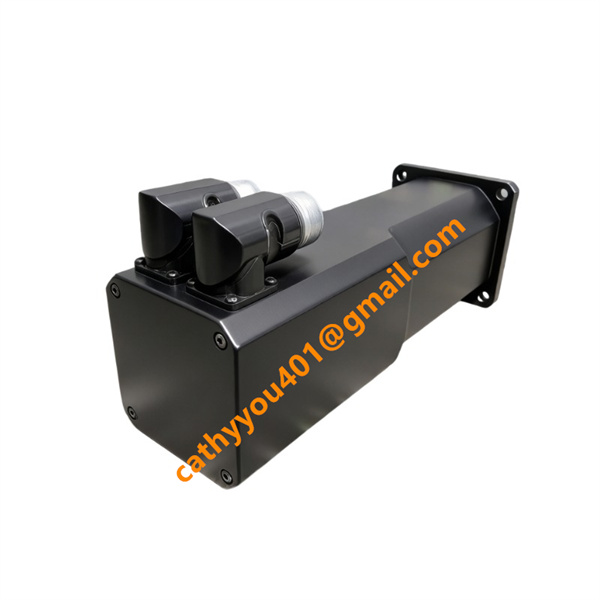
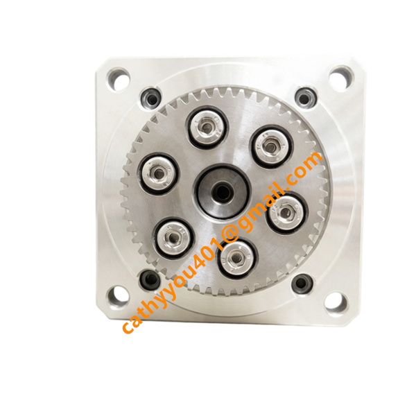







Description
-
BrandB&R
-
Model8MSA3X.E0-31
-
Product NameAustria
-
Place of Origin8MSA3 Series Permanent Magnet Synchronous AC Servo Motor
-
HS Code8501520000
-
Dimensions80mm*210mm*mm
-
Weight4.5 kg
-
Operating Temperature-20°C to +60°C
-
Storage Temperature-40°C to +85°C
-
Power Supply24VDC
-
Warranty12 month
-
Product StatusNew and original
B&R 8MSA3X.E0-31 Voltage & Current

Mounting Method of B&R 8MSA3X.E0-31
Standard Mounting Structure
The servo motor features an 80mm square IEC IM B5 front flange, compatible with horizontal, IM V1 vertical upward and IM V3 vertical downward mounting. Foot mounting design is not equipped.
Mechanical Assembly Steps
Insert the standard keyed motor shaft into couplings or reducer input ends. Attach the flange closely to the equipment mounting plate, then tighten four flange bolts with standard torque to remove axial gaps. Elastic couplings are advised for vibration damping; rigid direct connection with heavy loads is prohibited.
Heat Dissipation & Clearance Rules
The motor adopts natural air cooling with no built-in fan. Maintain a 40mm minimum clearance around the aluminum shell for ventilation. Do not block heat-dissipating surfaces or install the motor close to high-temperature components.
Grounding and EMC Requirements
Finish protective earthing at the grounding terminal on the motor flange prior to wiring. Deploy shielded cables for power and encoder lines, and ground cable shields at the metal machine frame with single-point grounding. Route power and encoder cables separately to reduce signal interference.
Connector Installation Notes
Independent straight power and encoder connectors are placed on the motor side. Leave sufficient side space to plug and unplug cables without sharp bending of connectors. Do not mount the motor with connectors facing down to prevent liquid ingress damage.
Environmental Restrictions
Only for indoor workshop application with ambient temperature ranging from -20°C to +60°C. Keep away from locations with massive cutting fluid splashes, corrosive gas and persistent strong vibration. Undamaged shaft oil seals are required to maintain IP65 protection when installed vertically.
Maintenance Tips
Cut off drive power before disassembly. Periodically inspect the tightness of flange bolts and the integrity of shaft seals during long-term running.