




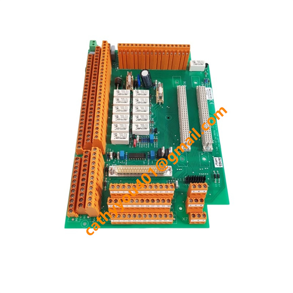







Description
-
BrandROLLS-ROYCE
-
Model5880-PC1011
-
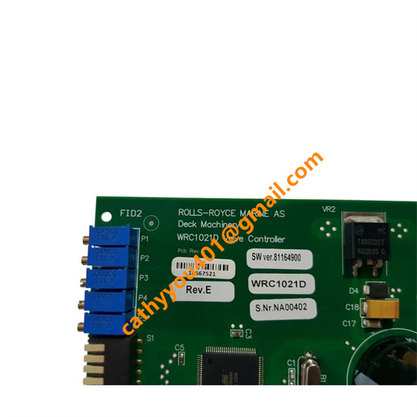
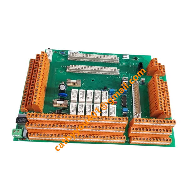
Product NameSteering Gear Control Circuit Board
-
Place of OriginNorway
-
HS Code85381090
-
Dimensions220 mm × 115 mm × 35 mm
-
Weight0.65 kg
-
Operating Temperature-10 °C to +55 °C
-
Storage Temperature-40 °C to +70 °C
-
Power Supply24 V DC
-
Warranty12month
-
Product StatusNew and original
Backed by abundant in-stock inventory and nearly 20 years of industry experience, our company stands as a leading player in the industrial control sector.We offer an extensive range of industrial control products covering numerous models. Should you have any other requirements, please feel free to contact us, and we will respond to you promptly.
Our main brand:
1.ABB's module cards, touch screens, controllers, etc., such as PP846 touch screen, IGCT starting with 5SHY, PM starting controller, AI, DO starting input/output module, SP starting Bailey module, etc
2.GE's module card CPUs, such as VMIC starter, IS200, IS215, IS400, IS420 series, etc,
3.Emerson's card components and EPRO probes, Westinghouse 1C series, Honeywell CC series, Schneider 140 series, Envision full series, Bentley 3500 series, Rexroth motors and drives, and Foxboro small modules.
Pre-Installation Safety & Inspection
Execute lock-out/tag-out protocols and completely cut off the 24 V DC control power of the steering gear prior to any work. Wear an anti-static wrist strap to avoid electrostatic discharge damage to electronic components.
Carry out visual examination of the PCB to check for transit damage, bent pins, corrosion and faulty components. Verify that the part number and hardware revision are consistent with the original unit to ensure system compatibility. Take photos of the existing wiring arrangement for reference during replacement.
Installation & Wiring
Install the PCB inside the steering control cabinet in a well-ventilated area, keeping it clear of heat sources, direct water splashes and intense vibration. Fasten the board uniformly; do not over-tighten screws to prevent circuit board distortion.
Wire all terminals strictly in accordance with the official steering gear wiring diagram. Separate signal cables from power cables to minimise electromagnetic interference. Tighten all terminal connections firmly to avert loose contacts induced by vessel vibration. Double-check bridge steering command inputs, rudder angle feedback circuits, control outputs for actuators and alarm signal wiring.
Power-on and Commissioning
Restore the control power supply once all wiring checks are finished. Monitor status indicators on the board and confirm no hardware fault alarms are activated.
Run static signal tests to validate normal reception of steering commands from the bridge and precise rudder angle feedback.
Conduct full-stroke rudder operation tests: steer the rudder from port to starboard, and verify stable closed-loop rudder position control as well as responsive control signals sent to hydraulic actuators.
Confirm proper alarm generation and data communication with vessel automation systems. Adjust relevant parameters if irregular steering response is detected.
Normal Operation Guidance
This PCB serves as the core component of the rudder control loop during ship navigation. Operators should continuously observe steering performance and system alarm notifications on the bridge.
In case of steering offset, signal interruption or fault alerts, first inspect PCB terminals, feedback sensors and power supply before additional troubleshooting. Altering circuit tracks or soldering components on the board without professional approval is prohibited.
Routine Maintenance
Perform visual inspections on every voyage. Clear accumulated dust, grease and salt residue using dry compressed air. Do not spray liquid cleaning agents directly onto chips and connectors.
Regularly inspect terminals for oxidation and looseness. Clean or replace corroded connectors in a timely manner.
Reduce long-term exposure to high humidity and salt fog inside the control cabinet to prolong the service life of the module.
Precautions
Never remove or install the PCB when power is switched on.
Avoid bending or applying extrusion force to the circuit board during handling.
This unit is an exclusive OEM spare part for Rolls-Royce Tenfjord steering gear automation systems. Incorrect application may result in steering system failure.
It is applicable to new shipbuilding projects, vessel retrofits and onboard spare part replacement.
Tenfjord steering control system for various commercial ships, engineering ships and marine engineering ships;
Ship servo signal acquisition, position closed-loop control, hydraulic rudder execution drive logic processing;
Rudder control cabinets for offshore supply ships, tugboats, passenger roll on/roll off ships, and offshore platform workboats;
Marine ship engine room automation, servo monitoring and control signal conditioning unit.
Frequently Asked Questions (FAQ)
1.How fast will you reply to my inquiry?
We process all inquiries efficiently and will respond promptly once we receive your message.
2.Do you carry large inventory of industrial control parts?
We maintain massive ready stock of mainstream automation spare parts to shorten lead times.
3.Can you source discontinued or obsolete PLC & DCS modules?
Absolutely.
We specialize in sourcing hard-to-find, obsolete and out-of-production industrial control components.
4.Do you inspect goods before shipment?
Every product undergoes thorough inspection before packing and dispatch.
5.Can you ship orders worldwide?
We provide global shipping with flexible logistics for urgent and regular orders.
6.What payment methods are available?
We accept multiple secure payment options. Please contact our sales team for detailed terms.