





19F53BD5DB6C497EB356240B8F7D7AED.jpg)
.jpg)
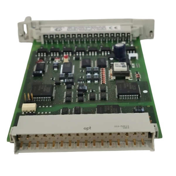







Description
-
BrandHIMA
-
ModelF6217
-
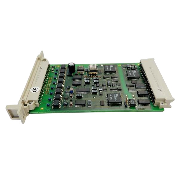
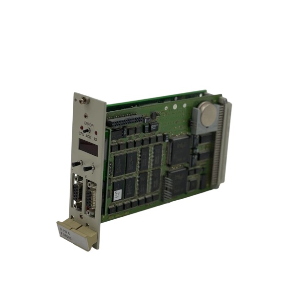
Product Name8‑Channel Safety‑related Analog Input Module for HIQuad Safety PLC System
-
Place of OriginGermany
-
Customs HS Code85389000
-
Power Supply0.25 A
-
Dimensions210 mm × 128 mm × 21 mm
-
Weight0.14 kg
-
Operating Temperature‑20 °C to +60 °C
-
Storage Temperature‑50 °C to +90 °C
-
Warranty1 year
-
Product Statusnew
Technical Specifications of HIMA F6217
Channel Configuration: 8 independent analog input channels
Supported Signal Types: 0–22 mA current signal (4–20 mA standard with 250 Ω shunt resistor); 0–5.5 V DC voltage signal
Maximum Input Voltage: 7.5 V DC
Maximum Input Current: 30 mA
Resolution: 12-bit
Voltage Channel Input Resistance: 100 kΩ
Data Update Cycle: 50 ms
Safety Response Time: Less than 450 ms
Input Filter Time Constant: Approximately 10 ms
Basic Accuracy Error: 0.1% full scale (25 °C)
Operating Accuracy Error: 0.3% full scale
Safety Error Limit: 1% full scale
Dielectric Withstand Voltage: 200 V (to ground)
Power Supply Requirements
Backplane Bus Power: 5 V DC, 80 mA
Auxiliary Power: 24 V DC, 50 mA
Safety & Performance Characteristics
Safety Certification: SIL 3 compliant per IEC 61508, AK6 safety qualification
Diagnostic Functions: Supports channel abnormality detection, circuit short-circuit and wire break diagnosis, comprehensive internal self-diagnosis, and system bus fault alarm reporting
Communication Interface: Dedicated HIMA internal I/O bus for data interaction with safety CPU
Protection Class: IP20 (cabinet indoor installation)
Industry Certifications: TÜV, CE, UL certified

Wiring Method for HIMA F6217
General Wiring Description
The F6217 safety analog input module uses the dedicated Z7127 front-terminal block for field-side signal wiring, while its rear-side plug connects to the HIMA system backplane bus. It is compatible with H41q and H51q safety systems and provides 8 fully independent analog input channels. Shielded twisted-pair cables shall be used for all field analog signals. Cable shields shall be single-point grounded to the cabinet equipotential bar to avoid ground-loop interference.
4-20 mA Current Signal Wiring (Two-wire Transmitter)
A 250 Ω precision shunt resistor must be fitted on the Z7127 terminal adapter, which converts the 4-20 mA current signal into a 1-5 V voltage signal for module processing.
Two-wire transmitter positive terminal → channel positive terminal
Two-wire transmitter negative terminal → channel negative terminal (analog GND)
The 24 V DC power supply for field transmitters must be provided externally; the F6217 module cannot supply power to field devices.
Every current channel works independently. Do not share analog ground between different channels.

Voltage-signal Wiring (0-5.5 V DC)
Signal positive wire connects to the channel positive terminal.
Signal negative wire connects to the corresponding channel analog GND terminal.
The external input voltage must never exceed the module maximum rating of 7.5 V DC.
Backplane and Auxiliary Power Wiring
5 V DC power is automatically supplied through the system backplane bus once the module is inserted; no additional field wiring is needed, with typical power consumption of 80 mA.
24 V DC auxiliary power is wired to the dedicated auxiliary terminals on Z7127, rated consumption 50 mA. Strict polarity observance is mandatory.
PE protective earth: connect cabinet protective ground to the grounding pin of the Z7127 connector.
Termination Requirements for Unused Channels
For unused voltage-input channels: fit short-circuit jumpers across the corresponding positive and negative terminals to suppress open-circuit diagnostic alarms.
For unused current-input channels: retain the installed 250 Ω shunt resistor, or apply short-circuit termination following the official adapter specifications.



.jpg)







