.jpg)
774A4855C16A41259809CB93A063B56E.jpg)
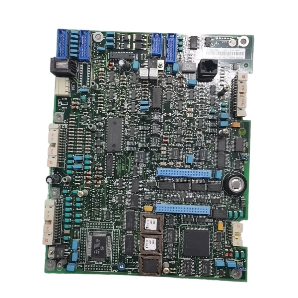







Description
-
BrandABB
-
ModelSDCS-CON-1
-
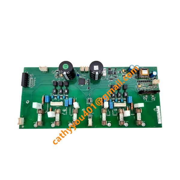
Product NameDC Drive Control Board
-
Place of OriginFinland
-
Customs HS Code85423190
-
Part number3BSE006196R1
-
Dimensions234mm × 160mm × 30mm
-
Weight0.42kg
-
Operating Temperature0℃ to +55℃
-
Storage Temperature-40℃ to +85℃
-
Warranty12 month
-
Product Statusnew
ABB SDCS-CON-1 (3BSE006196R1) I/O, Voltage and Current Specifications
Note: The SDCS-CON-1 functions as the central CPU control board for DCS500 and DCS600 series DC drives. There are no direct field-wirable I/O terminals on this board. All external digital and analog signals are transmitted to auxiliary I/O modules (SDCS-IOB-1 / SDCS-IOB-2 / SDCS-IOB-3) over the DDCS flat-cable bus.
Internal Board Power Supply (Power supplied via backplane from SDCS-POW-1 power board)
Operating input power for SDCS-CON-1: 24 VDC (backplane feed)
On-board secondary power rails: +5 V, ±15 V (for internal logic circuitry only; external field loads cannot be connected)
Typical power dissipation: ~10 W; typical operating current: 0.3-0.4 A at 24 VDC
On-board Encoder & Tachometer Interface (connector signals extended to IOB board)
Incremental encoder power: 5 V or 24 V user-selectable
Maximum output current for encoder supply: 250 mA (5 V); 200 mA (24 V)
Analog tachometer differential input: maximum ±270 V
Electrical Characteristics of SDCS-IOB-1 (Standard Matching I/O Board)
Digital Inputs (8-channel)
Logic level: 24 VDC
Logic-0 threshold: -3 V+5 V; Logic-1 threshold: +15 V-+30 V
Typical channel input current (@24 V): 5 mA
Absolute maximum input voltage: 30 VDC

Digital Outputs (7-channel, open-collector)
Reference supply: 24 VDC
Maximum continuous current per channel: 0.1 A
Total combined maximum current for all outputs: 0.4 A
Built-in short-circuit protection is absent; external fuse is mandatory.
Analog Inputs (5-channel)
Programmable signal ranges: -10 V…+10 V, 0-10 V, 0-20 mA, 4-20 mA
Input impedance: >200 kΩ (voltage mode); 250 Ω (current mode)
Conversion resolution: 12-bit
Analog Outputs (2-channel)
Programmable signal ranges: -10 V…+10 V, 0-20 mA, 4-20 mA
Max load current under voltage mode: ±5 mA
Maximum burden resistance for current output: 500 Ω
Conversion resolution: 12-bit
Communication Interfaces
Operator panel interface for CDP-31x: 2-wire RS-485
DDCS flat-cable bus (connects to IOB modules): 4 Mbps baud rate

Operating Guide for ABB SDCS-CON-1 (3BSE006196R1)
The SDCS-CON-1 serves as the core main control board for ABB DCS500 and DCS600 DC drive systems. It cannot operate on a standalone basis and shall be mounted inside the DC drive cabinet for normal function.
Pre-Installation Safety Precautions
Disconnect both main power supply and control power of the drive system prior to any handling work.
Comply with ESD anti-static requirements; wear an anti-static wristband to prevent electrostatic breakdown of onboard electronic components.
Cross-check the part number SDCS-CON-1, 3BSE006196R1. Confirm hardware compatibility with your existing DCS500 or DCS600 power unit. This board is not applicable to other drive product ranges.
Installation Procedures
Open the drive cabinet and identify the dedicated slot reserved for the main control unit.
Line up the onboard connector against the backplane socket, insert the circuit board securely and fasten the fixing screws.
Hook up associated wiring including operator panel cable, I/O terminal wiring, encoder feedback line and RS-485 communication cable.
Inspect all plug-in connectors to ensure full insertion, free from loose contacts or skewed pins.
Power-Up and Commissioning Workflow
Secure the cabinet door. Energize the 24 VDC control power first, followed by the high-voltage main power.
Attach the ABB CDP-31x operator panel to SDCS-CON-1; startup status codes will be presented on the panel display.
Configure drive parameters from the operator panel: motor nameplate information, speed thresholds, acceleration-deceleration ramps and I/O function assignment.
Execute motor identification run as required to finish automatic tuning of control loop parameters.
Choose control mode: local control via operator panel or remote control through hardware terminals / fieldbus interface.
Daily Operating Modes
Local operation: Realize start-stop commands and speed setpoint adjustment with the CDP-31x operator panel.
Remote operation: Trigger run-stop signals and transmit speed reference via hard-wired digital/analog I/O or RS-485 communication link.
This control board implements closed-loop speed and torque regulation, processes feedback signals and carries out drive fault diagnosis. Relevant fault codes will pop up on the operator panel once malfunctions arise.
Fault Diagnosis and Board Replacement
Record fault codes shown on the operator panel when malfunctions occur.
Cut off all power completely before dismounting the defective control board.
After installing a new SDCS-CON-1 module, restore previously backed-up parameters. Reboot the system and validate motor running performance.

GDB021BE
Unitrol 1020
698B275U01
SM810K01
BC810K02
PP886
PBA800
RED615