




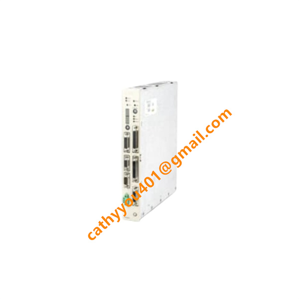







Description
-
BrandABB
-
ModelPM655
-
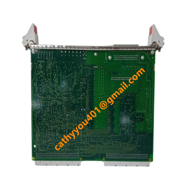
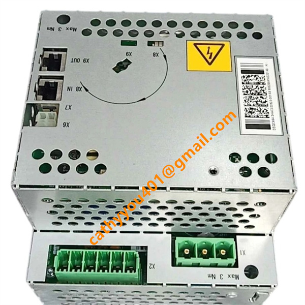
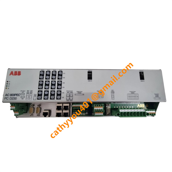
Product NamePM655 Processor Unit for AC 800M Controller
-
Place of OriginSweden
-
HS Code85389000
-
Dimensions35 mm × 130 mm × 130 mm
-
Weight0.48 kg
-
Operating Temperature0 °C to +60 °C
-
Storage Temperature-40 °C to +85 °C
-
Power Supply18 V DC to 30 V DC
-
Warranty12 month
-
Product StatusNew and original
Backed by abundant in-stock inventory and nearly 20 years of industry experience, our company stands as a leading player in the industrial control sector.We offer an extensive range of industrial control products covering numerous models. Should you have any other requirements, please feel free to contact us, and we will respond to you promptly.
Our main brand:
1.ABB's module cards, touch screens, controllers, etc., such as PP846 touch screen, IGCT starting with 5SHY, PM starting controller, AI, DO starting input/output module, SP starting Bailey module, etc
2.GE's module card CPUs, such as VMIC starter, IS200, IS215, IS400, IS420 series, etc,
3.Emerson's card components and EPRO probes, Westinghouse 1C series, Honeywell CC series, Schneider 140 series, Envision full series, Bentley 3500 series, Rexroth motors and drives, and Foxboro small modules.
Equipped with 8 channels of 24 V DC transistor-type digital outputs, the PM655 is engineered to actuate solenoid valves, signal lamps, miniature contactor coils and an extensive range of low-power discrete field actuators.
Each output channel supports a maximum load of 0.5 A, while the aggregated total output current is capped at 4 A.
Onboard short-circuit and overload protection alongside intelligent current limiting are implemented; the circuit can automatically resume normal operation once faults are cleared.
A built-in varistor protection circuit effectively suppresses back EMF generated by inductive loads, safeguarding circuitry and prolonging the operational lifespan of output channels.
Individual channel LED status indicators enable instant visual check to confirm whether control commands are executed properly.
Flexible switching frequency configuration is available for resistive, lighting and inductive loads, allowing seamless adaptation to varied actuator specifications.

Pre-Commissioning Inspection
Before powering on the PM655, complete a full hardware inspection. Ensure the controller is securely mounted on the DIN rail. Check all power terminals, I/O wiring, communication ports and grounding per electrical drawings. Separate power cables from analog signal cables to avoid electromagnetic interference. Confirm the input power voltage meets the rated requirement, and isolate all field sensors and actuators for safe initial power-up.
Step 1: Power-Up & Hardware Self-Check
Apply power to the controller and check the front-panel power LED for steady illumination with no fault alarms. Inspect for overheating, flickering lights or abnormal noise. Power off immediately and resolve any hardware errors if faults occur. Wait 2–3 minutes for the device to finish system self-diagnosis and full startup.
Step 2: Communication & Software Connection
Connect your PC to the PM655 via Ethernet. Open ABB Automation Builder or Control Builder M, and set the PC IP address to match the same network segment. Scan and establish a stable online connection with the controller. Verify the device model, serial number and firmware version, and update the firmware if required.
Step 3: Project Configuration Download
Check and confirm all project settings, including hardware configuration, I/O mapping, network parameters and task cycle settings. Eliminate all program errors and warnings. Download the system configuration and control program to the PM655, then reboot the controller to activate all parameters.
Step 4: Digital Input (DI) Testing
Enter online monitoring mode. Manually trigger field devices such as limit switches, pushbuttons and proximity sensors one by one. Verify real-time DI status updates in the software and corresponding channel LED indicators. Adjust input filter time to eliminate signal jitter and contact bounce, and record and fix any abnormal channels.
Step 5: Digital Output (DO) Testing
Use the software force function to test each 24V DC transistor output channel sequentially. Check the operation of solenoid valves, indicator lamps and small contactors. Ensure each channel works within the 0.5A single-channel limit and 4A total output limit. Verify built-in short-circuit and overload protection, as well as varistor surge protection for stable operation of inductive loads.
Step 6: Analog I/O Calibration
Calibrate analog inputs by applying standard 0–10V, 4–20mA signals and simulating RTD temperature sensors. Correct offset errors if measurement deviation occurs. For analog outputs, set different output values in the program and test actual voltage/current output to ensure precise 12-bit resolution control for inverters and proportional valves.
Step 7: High-Speed I/O & Pulse Function Test
Test the integrated high-speed counter by connecting encoders. Verify accuracy in speed measurement, position tracking and length counting. Check that PWM and pulse signal acquisition functions work normally under different frequency parameters.
Step 8: Control Logic & Interlock Debugging
Release all manual force commands and enable automatic program operation. Test control sequences, safety interlocks, timing logic and PID closed-loop control. Simulate abnormal working conditions to verify alarm and fault handling functions. Optimize PID parameters, filter settings and switching frequency according to actual operating performance.
Step 9: System Integration & Stability Test
Complete communication debugging with HMI, drives and peripheral devices to ensure consistent data transmission. Run a minimum 2-hour continuous no-load test. Monitor CPU load, network status and I/O refresh conditions to confirm no signal drift, disconnection or program shutdown issues.
Step 10: Commissioning Finish & Data Backup
After full function acceptance, back up the complete project file, including all configuration parameters, alarm settings and optimized control data. Save all test and troubleshooting records. Train on-site operators for daily monitoring and basic fault maintenance before project handover.

Frequently Asked Questions (FAQ)
1.How fast will you reply to my inquiry?
We process all inquiries efficiently and will respond promptly once we receive your message.
2.Do you carry large inventory of industrial control parts?
We maintain massive ready stock of mainstream automation spare parts to shorten lead times.
3.Can you source discontinued or obsolete PLC & DCS modules?
Absolutely.
We specialize in sourcing hard-to-find, obsolete and out-of-production industrial control components.
4.Do you inspect goods before shipment?
Every product undergoes thorough inspection before packing and dispatch.
5.Can you ship orders worldwide?
We provide global shipping with flexible logistics for urgent and regular orders.
6.What payment methods are available?
We accept multiple secure payment options. Please contact our sales team for detailed terms.
7.Do you offer warranty on industrial control spare parts?
Warranty differs by product.
Confirm specific warranty details with us prior to ordering.
8.Are your automation parts new or used?
We supply both new and fully tested used industrial control spare parts.
Please state your needs in your inquiry.
9.What is your typical delivery lead time?
In-stock items can be shipped quickly.
We will advise exact lead time for out-of-stock products after stock verification.
10.Can you offer technical support to check model compatibility?
Yes.Our professional team provides technical support to verify specifications and model compatibility.