




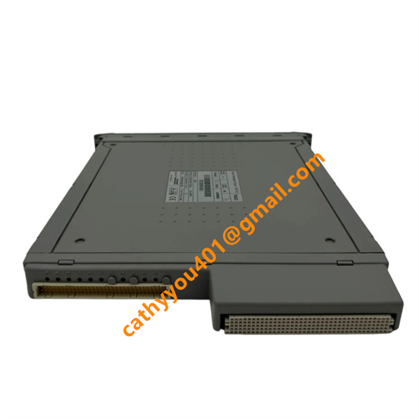


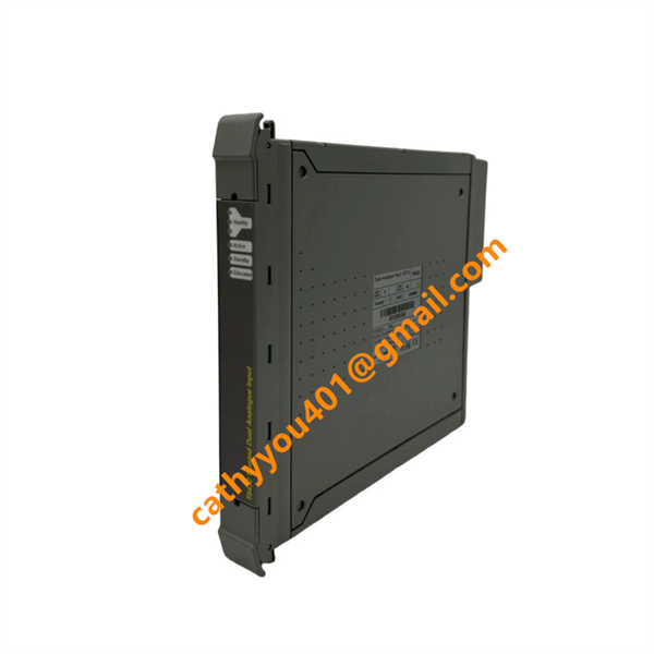







Description
-
BrandICS Triplex
-
ModelT8432
-
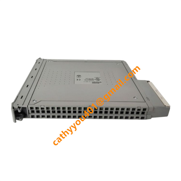
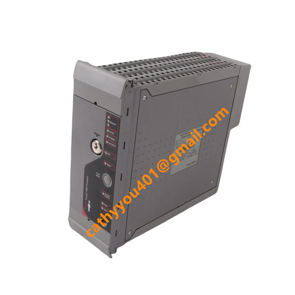
Product NameDual Analogue Input Module
-
Place of OriginUnited Kingdom
-
HS Code8542319000
-
Dimensions56 mm × 86 mm × 56 mm
-
Weight0.15 kg
-
Operating Temperature-20 °C to +70 °C
-
Storage Temperature-40 °C to +85 °C
-
Power Supply24VDC
-
Warranty12 month
-
Product StatusNew and original
ICS Triplex T8432 Input & Output Specifications
Analog Input
This is a dual-channel pure analog input module with no physical hard output channels.
It supports two standard industrial analog signal types: 0–20 mA current input and 0–10 V voltage input.
It adopts 16-bit high-precision sampling resolution with ±0.02% full-scale accuracy and 10 kHz high-speed sampling rate, ensuring accurate and real-time collection of field analog signals from transmitters and sensors.
The input circuit features anti-interference and isolation design, which effectively filters industrial field noise and guarantees stable signal acquisition.

Internal System Output
The module converts collected analog field signals into standard digital data and transmits the processed digital data to the Triconex safety controller via the built-in RS-485 bus interface.
It only realizes internal system data output and communication transmission, without external analog, relay or switching physical output contacts.
Power Input
The module is powered by the system rack backplane with a rated 5 V DC power supply and typical working current ≤ 10 mA. No external power input is required.

ICS Triplex T8432 Installation Method
Pre-installation Preparation
Completely power down the entire SIS system before installation. Inspect the T8432 module for surface damage, contamination and defective connectors. Check and clean the target rack slot to ensure full compatibility. Reserve adequate ventilation space and arrange the module away from high-power devices and strong electromagnetic interference to guarantee stable signal acquisition.
Module Rack Installation
Equipped with an anti-misplug structure, the T8432 supports standard rack backplane mounting. Align the module horizontally with the empty slot, insert it smoothly and push firmly until it fully locks with the backplane connector. Tighten the front fixing screws securely to prevent looseness and vibration during system operation.

Field Analog Wiring
Route and connect field 0–10 V voltage and 0–20 mA current analog signals in strict accordance with circuit diagrams. Ensure correct polarity with no short circuits, open circuits or loose terminal connections. Separate signal cables from power cables to minimize electromagnetic interference. Arrange wires neatly and avoid excessive tension, compression and sharp bending.
Pre-power-on Inspection
Confirm the module is fully inserted and firmly fixed. Verify all analog wiring is accurate and intact. Ensure ventilation openings are unobstructed, and the installation environment complies with temperature, humidity and IP20 protection standards. Remove all potential circuit safety hazards before powering on.
Power-on & Commissioning
Restore system power, as the module is powered by 5 V DC rack backplane power supply. Check module status indicators for normal operation after power-on. Upon system initialization, complete analog channel signal testing and data verification to confirm accurate field signal collection and stable digital data transmission, completing the entire installation and commissioning process.