





.jpg)
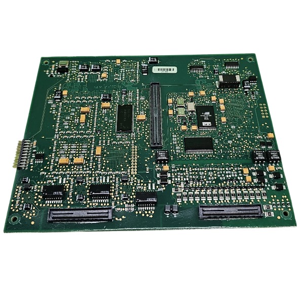







Description
-
BrandTRICONEXN
-
Model30056E
-
Product NameSafety System Processor Module
-
Place of OriginUnited States
-
Customs HS Code85371011
-
Power Supply0.65 A
-
Dimensions220mm × 130mm × 55mm
-
Weight0.72 kg
-
Operating Temperature-20°C ~ +70°C
-
Storage Temperature-60°C ~ +90°C
-
Warranty1 year
-
Product Statusbrand new
Working Principle of Triconex 30056E
1. Core TMR Architecture Principle
This module features a strict triple modular redundant structure. Three completely independent signal processing channels operate in parallel to sample the identical field input signal. Each channel is equipped with a dedicated signal conditioning circuit, independent A/D converter and standalone processing logic, with no mutual interference.
Three groups of converted digital data are uploaded to the Tricon main controller, which executes **2-out-of-3 voting logic** and adopts the median valid value as the final process signal. If one channel generates abnormal and deviated data while the other two work normally, the faulty channel will be automatically isolated. The system maintains continuous and stable operation via the remaining healthy channels and outputs a diagnostic alarm to prompt maintenance. This TMR design completely eliminates single-point failures and avoids safety system misoperation or unexpected tripping.
2. Analog Signal Acquisition and Conditioning
Field 4–20mA current signals from process transmitters are imported into the module terminals. The built-in high-precision signal conditioning circuit converts analog current signals into standard voltage signals applicable for A/D conversion.
Integrated surge suppression and EMC protection circuits effectively filter transient voltage surges, industrial electromagnetic interference and field loop noise. The three redundant A/D units perform synchronous and independent high-precision sampling and convert analog process signals into standard digital data for subsequent voting calculation.
3. Channel Diagnostic Mechanism
The 30056E supports full-time continuous self-diagnosis for all input channels and internal hardware:
Open circuit detection: Identifies cable breakage, transmitter failure or power loss (signal below 4mA).
Short circuit detection: Detects field wiring short faults (signal above 20mA).
Internal hardware monitoring: Real-time inspection of reference voltage, A/D circuit status and synchronous communication status among three redundant channels.
All diagnostic results are uploaded to the Tricon main controller and displayed visually in TriStation software. Abnormal fault information will trigger system alarms to facilitate timely troubleshooting and maintenance.
4. Data Communication with Tricon Main Controller
After signal conditioning, A/D conversion and pre-diagnosis, three sets of independent digital data are transmitted to the Tricon triple main processor through the high-speed backplane bus. The main controller completes data voting and verification, and applies the final valid process value for safety logic operation, process interlock judgment and ESD trip control.
Meanwhile, the module receives synchronous timing and control commands from the main controller to ensure consistent sampling rhythm and data synchronization of the three redundant channels.
5. Isolation and Safety Features
Galvanic isolation is implemented between the field instrument side and the internal TMR logic circuit. It effectively isolates on-site ground potential differences and industrial noise interference, protecting the SIS main system from field circuit faults.
The module supports HART pass-through function, which enables real-time collection of 4–20mA analog process variables while allowing HART digital signal communication, supporting remote configuration, parameter adjustment and fault diagnosis of field smart transmitters.
6. Functional Boundary
The 30056E is only responsible for field analog signal acquisition, conditioning, conversion and on-board pre-diagnosis. It does not undertake safety logic operation and interlock judgment. All core functions including data voting, safety logic calculation and trip execution are completed by the Tricon main controller. The module complies with IEC 61508 SIL safety standards and is fully applicable to critical SIS safety loops.
7. Fault Tolerance Logic Summary
Single channel failure: The voting result remains valid, the system outputs a maintenance alarm, and the safety loop operates normally without shutdown.
Dual or triple channel failure: The system marks the corresponding process point as invalid and executes preset safety protection actions according to system logic.

Commissioning Steps for Triconex 30056E
1. Pre-commissioning Inspection
Disconnect all power sources prior to any operation. Carry out visual inspection on the 30056E module to check for physical damage, scratches or damaged connectors. Examine the integrity of the backplane and confirm the module is compatible with the Triconex Tricon system. Verify the 24VDC system power supply stays within its rated tolerance. Confirm all field wiring is finished; all cables shall be shielded and properly grounded. Inspect field signal loops for short circuits and insulation defects.
2. Module Installation
Insert the 30056E module into the assigned slot on the Tricon backplane. Fasten the module retaining latches to guarantee reliable contact with the backplane. Ensure the module is fully seated in the slot without loose pins. Complete field signal wiring to the module terminal assembly. Route power cables and signal cables separately to minimize electromagnetic interference. Implement 360° shield termination on all signal cables to satisfy EMC requirements.
3. Hardware Configuration via TriStation
Open the TriStation engineering software and load the target Tricon project. Add the 30056E module into the hardware tree, and specify the correct slot position as well as module firmware revision. Configure channel types, signal ranges, fault detection parameters and voting settings in accordance with P&ID drawings and safety specifications. Download the compiled hardware configuration and application logic to the Tricon main controller.
4. Power-up and Initial Module Check
Power on the Tricon chassis and the 30056E module. Observe LED indicators on the module front panel. Confirm the power LED is lit and no fault LEDs are activated. Switch to online mode in TriStation to validate that the system detects the 30056E module. Check module status, firmware version and channel health in the diagnostic menu. Eliminate any module mismatch or communication faults before moving to subsequent steps.
5. Channel Point-to-Point Test
Conduct loop testing for every channel. Apply simulated field signals to input channels and validate that corresponding values are displayed accurately within TriStation. Verify channel fault alarms such as wire break and short-circuit detection. Confirm the triple modular redundancy (TMR) voting function operates normally for all signals. Document all test results for safety compliance records.
6. Logic and Interlock Test
Run offline simulation first to verify safety logic sequences. Perform online functional tests for safety interlocks, emergency shutdown and trip functions. Simulate abnormal process conditions to confirm the system executes correct trip actions. Validate that interlock response time meets safety system requirements. Rectify any logic mismatch or abnormal channel performance.
7. System Full Commissioning and Documentation
Upon successful point test and interlock test, carry out full system hot commissioning while the process is on standby. Keep continuous monitoring of module diagnostic status and signal quality. Save the final project, hardware configuration and all commissioning reports. Create a complete system backup on the engineering workstation. Deliver test records, drawings and parameter files to the on-site maintenance team.


.jpg)


.jpg)







