





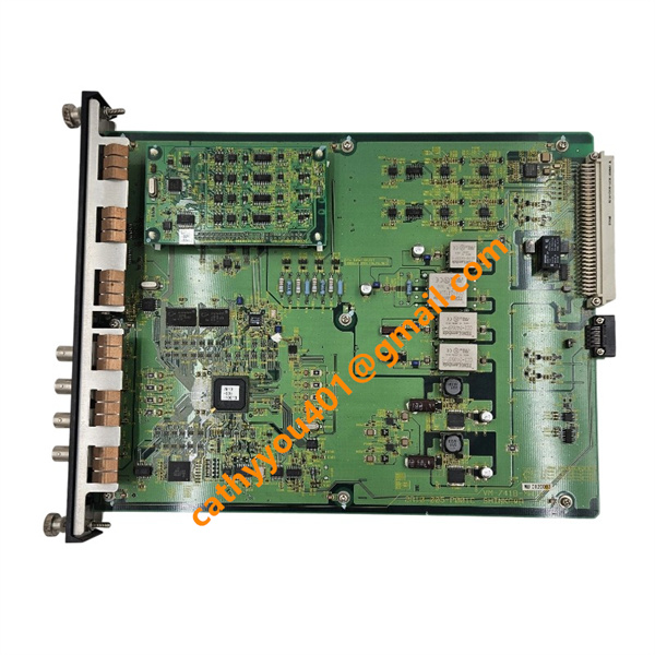
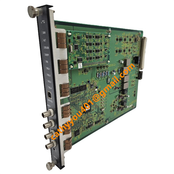







Description
-
BrandShinkawa
-
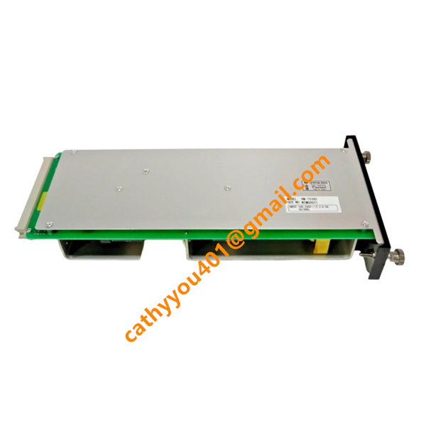
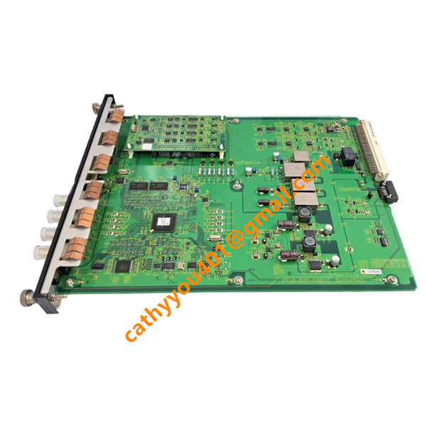
ModelVM-741B/TB1
-
Product NameLocal Communication & Phase Marker Module
-
Country of OriginJapan
-
HS Code8538900090
-
Dimensions200mm×140mm×90mm
-
Weight600g
-
Operating Temperature-10℃ ~ +70℃
-
Storage Temperature-25℃ ~ +85℃
-
Power Supply24VDC
-
Warranty12 month
-
Product StatusNew and original
SHINKAWA VM-741B/TB1 Technical Specification & Product Profile
Electrical Technical Parameters
Power Supply
Rated Operating Voltage: 24 VDC (standard power input of VM-7 series rack power module)
Power Consumption: ≤18W
Signal Input & Output
1. Phase Marker Input Signal: Max input amplitude ≤ 50 Vp-p; support rotational speed up to 60,000 RPM
2. Buffered Phase Marker Output: Isolated 0–5VDC pulse signal for secondary equipment acquisition
3. Alarm Relay Output: 6 groups SPDT dry contact relays; contact capacity: 250VAC / 5A, 30VDC / 5A
4. Contact Reset Mode: Optional auto-reset or latch hold function, configurable on site
Communication Specifications
Local Bus: RS485 Modbus RTU protocol
Upper Network Transmission: 100Base-T Ethernet, Modbus TCP/IP protocol
Onboard Storage: 4MB memory for fault event history data backup

VM-741B/TB1 Shinkawa Standard Wiring Method
The suffix/TB1 configuration is equipped with 6-pin terminal block plugs (model: FRONT-MC-1.5/6-STF-3.81) for all I/O wiring, D-Sub connectors are not equipped, specific wiring steps and definitions are as follows:
Step 1: Pre-operation Preparation
Cut off the whole rack power supply, implement LOTO lockout safety operation, wear anti-static wrist strap to prevent static damage to circuit board components, confirm module fixed slot position in VM-761B instrument rack.
Step 2: Power Wiring
Terminal block positive pole (+): Connect 24VDC power supply positive terminal from rack VM-75B power module
Terminal block negative pole (-): Connect 24VDC power supply negative pole + equipment protective ground wire (PE grounding must be reliably connected)
Step 3: Phase Marker Signal Wiring
1. Phase Marker Signal Positive Terminal: Connect signal output wire from speed/phase sensor
2. Phase Marker Signal Common Ground Terminal: Connect shielding cable shielding layer single-point grounding
3. Buffered Phase Marker Output Terminals: Access secondary testing instrument or external acquisition equipment
Step 4: Alarm Relay Contact Wiring
Each group relay includes three terminals: Normally Open (NO), Common Terminal (COM), Normally Closed (NC)
Danger Alarm Signal: Access DCS alarm input channel via NO+COM terminals
Early Warning Alert Signal: Select NC+COM terminals according to field system configuration requirements
Step 5: Communication Cable Wiring
1. RS485 Modbus RTU: A line + B line connect to bus communication terminal block separately
2. Ethernet Communication: RJ45 front service interface connect to industrial switch via shielded network cable
Step 6: Post-wiring Inspection & Power-on Test
Check all terminal wiring tightening torque, cable shielding grounding treatment; restore rack power supply, observe steady-on green SYS-OK light, flashing COMM light represents normal communication transmission; simulate phase signal input to verify speed and alarm output function normally

VM-741B/TB1 Shinkawa Core Product Advantages
1. Centralized Rack Management Function: Collect all vibration, displacement, temperature monitoring data and alarm signals from each module inside the instrument rack, realize unified signal sorting and centralized alarm output。
2. High-precision Phase Marker Processing: Realize rotational speed measurement, 1X/2X harmonic phase analysis, vibration vector calculation via phase reference signals, critical for rotating machinery fault diagnosis and unbalance analysis。
3. Dual Communication Network Architecture: Compatible with both wired Ethernet and RS485 bus, seamlessly dock with DCS, PLC and industrial upper computer monitoring system to realize remote data uploading 。
4. TB1 Terminal Block Wiring Configuration: Comes complete with matched Phoenix terminal plug connectors, more stable for long-term industrial field wiring, stronger anti-vibration performance than D-Sub connectors, convenient for on-site wiring maintenance 。
5. Front Hot-swappable Structure: Supports plugging and unplugging modules directly from the front of the rack without back wiring disassembly, greatly shortening equipment maintenance downtime; supports redundant power supply matching to avoid system monitoring interruption caused by power failure 。
6. Industrial High Stability: Adopt tropical climate adaptive design, strong anti-electromagnetic interference performance, adapt to harsh working conditions of power plants and petrochemical industrial sites.