






Description
-
BrandKUKA
-
Model00-128-358
-
Product NameMFC+DSE Control Card
-
Place of OriginGermany
-
Customs HS Code85423190
-
Power Supply6mA
-
Dimensions102mm × 85mm × 42mm
-
Weight0.28kg
-
Operating Temperature-20°C to +55°C
-
Storage Temperature-40°C to +70°C
-
Warranty12 month
-
Product Statusoriginal
KUKA 00-128-358 MFC3 Multi-Function Board Technical Specifications
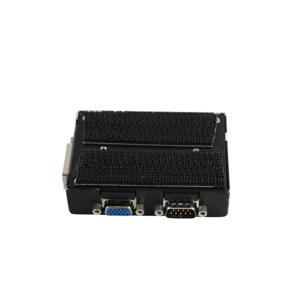
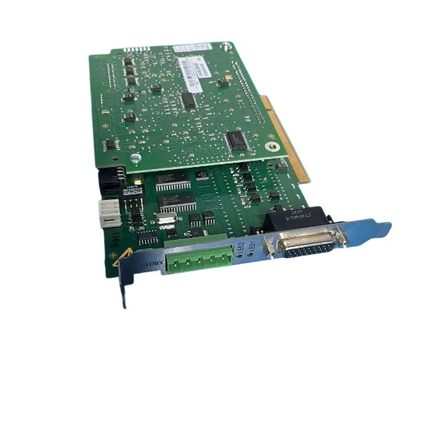
Part number 00-128-358 identifies the MFC3 multi-function mainboard, which acts as the core control motherboard for KUKA KRC2 Ed05 and VKRC2 Ed05 robot controller systems.
This mainboard supports a maximum of two DSE-IBS-C33 servo daughterboards (00-117-336) for extended servo control and bus communication functions. It integrates multiple core bus interfaces, including a parallel local bus for DSE daughterboard data interaction, a dedicated CAN bus for KCP teach pendant communication, and a DeviceNet CAN bus for external device connection.
The board features dual-channel safety signal monitoring, covering emergency stop signals, enabling switch signals and safety gate status signals to ensure robot operational safety. It undertakes core system tasks such as servo motion synchronization, safety logic judgment and processing, and internal signal interaction of the control cabinet.
It is fully compatible with KUKA system software versions KSS 5.2, KSS 5.4 and KSS 5.5. The mainboard is powered by the controller’s internal backplane power supply.
The MFC3 mainboard does not integrate any external user-defined digital or analog I/O interfaces. All peripheral I/O functions are realized through the matching CI3 safety board or extended external DeviceNet I/O modules. It establishes stable data communication and signal interaction with KPS power supply modules, CI3 safety boards, KCP teach pendants and RDC servo systems to support the overall normal operation of the robot controller.

KUKA 00-128-358 MFC3 Multi-Function Board Detailed Introduction
Applicable controller: KRC2 Ed05 / VKRC2 Ed05 robot controller
Core positioning: It serves as the core motion and safety interface motherboard within the KRC2 Ed05 controller, functioning as the communication bridge between the cabinet industrial PC, servo subsystem, safety circuit, teach pendant and fieldbus.
Daughterboard expansion: It supports up to two DSE-IBS-C33 servo daughterboards (00-117-336). These daughterboards plug into the backplane slots of MFC3 to enable Interbus-based servo communication.
Real-time processing: Fitted with an RTAcc real-time processor operating under the VxWin real-time kernel, it handles servo synchronization and cyclic safety signal detection.
Bus interfaces: Parallel local bus for communication with DSE daughterboards; CAN bus for KCP teach pendant; DeviceNet CAN bus master port for external field I/O and peripheral equipment; internal safety bus linking to the CI3 safety board.
Safety signal processing: Acquires dual-channel safety signals and generates test pulses. Monitored signals cover local emergency stop, external emergency stop, enabling deadman switch and safety guard door. It conducts cross-verification on dual-channel safety signals and forwards safety status to the CI3 board.
System signal management: Captures operating mode selector signals (T1 / T2 / AUTO); monitors the speed of three cabinet cooling fans; implements cabinet housing supervision, power supply and temperature monitoring; detects faults of DSE servo daughterboards; exchanges signals with the KPS power module and transmits drive contactor release requests.
I/O definition note: This standard MFC3 board has no externally accessible discrete DI/DO terminals for users. All signals routed through MFC3 are internal system, servo and safety signals. User-side 24V digital peripheral I/O is supplied by the CI3 board or external DeviceNet I/O modules.
Compatible software: KSS 5.2, KSS 5.4, KSS 5.5
Board version distinction: This is the MFC3 Standard variant, which does not support the RoboTeam CR safe robot group function. The CR capability is available on the MFC3 Tech version and requires pairing with a CI3 Tech board.
Diagnostic function: Onboard status LEDs indicate DeviceNet CAN bus and internal communication conditions for troubleshooting bus failures and board health status.
Signal direction: Receives input signals related to safety, fans, operating mode and system monitoring; outputs safety test pulses, drive contactor control requests, real-time synchronization clock for DSE cards and CAN bus data.


.jpg)