











Description
-
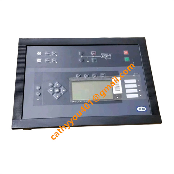
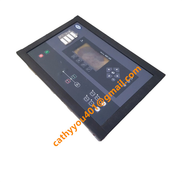
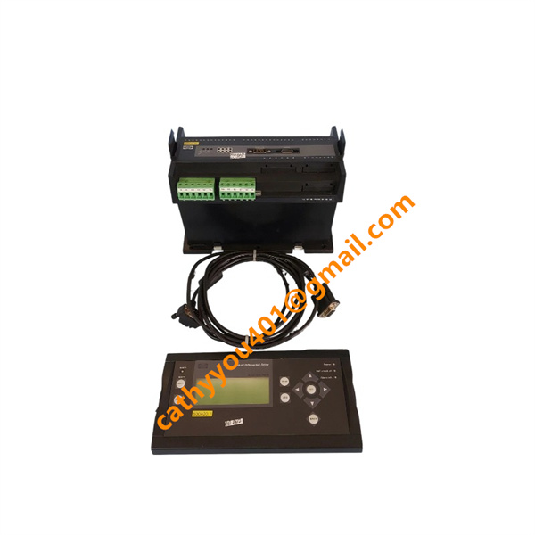
BrandDEIF
-
ModelMDR2
-
Product NameMulti Differential Protection Relay
-
Place of OriginDenmark
-
HS Code90303330
-
Dimensions144mm*160mm*115mm
-
Weight1.5 kilograms
-
Operating Temperature-40°C to +85°C
-
Storage Temperature25°C to +70°C
-
Power Supply24VDC
-
Warranty12 month
-
Product StatusNew and original
DEIF MDR-2 Voltage & Current Parameters
Auxiliary Power Voltage
Nominal auxiliary supply voltage: 12 V DC / 24 V DC
Continuous operating voltage range: 8 V DC to 36 V DC
Max power consumption: 11 W
CT Measuring Current Input
Compatible CT secondary rated current: 1 A or 5 A
Max single-phase power consumption per CT channel: 0.3 VA
Measurement accuracy: 1% full scale
Digital Input Voltage & Current
DI operating voltage range: 6 V DC to 32 V DC
Internal circuit impedance: 2.4 kΩ, bidirectional design
Relay Output Voltage & Current Rating
AC resistive load: 250 V AC, 8 A
DC resistive load: 24 V DC, 1 A

DEIF MDR-2 Wiring Method
Auxiliary DC Power Connection
Route the 12/24VDC power supply to the dedicated power terminals on Terminal Block 1. Strictly observe positive and negative polarities, and install a fuse on the power circuit to prevent short-circuit damage.
CT Secondary Current Connection
Connect CTs from the primary and secondary equipment sides to the current measuring terminals on Terminal Block 7. Terminals S1 (k) are for incoming signals and S2 (l) for outgoing signals. Select star or delta wiring according to the actual transformer configuration. The CT secondary circuit must be solidly grounded to eliminate dangerous induced high voltage.
Digital Input Connection
Run external signals including interlock, trip lockout and alarm reset to the opto-isolated digital input terminals 23–27. All digital input circuits share a common COM terminal, with a valid signal voltage range of 6–32VDC.
Relay Contact Output Connection
Terminal Blocks 2, 5 and 6 provide three sets of NO, NC and common relay contacts. Wire trip circuits and alarm signal circuits to matching terminals. Ensure the connected load does not exceed the rated capacity of 250VAC 8A or 24VDC 1A.
RS485 Communication Connection
Terminal 14 = A (signal positive), Terminal 15 = B (signal negative), Terminal 16 = shield earth. Use twisted shielded cables for wiring and attach cable shields to cabinet ground. The maximum bus length is 1000 meters, and a maximum of 32 units can be connected in parallel.
DU-2 Remote Display Connection
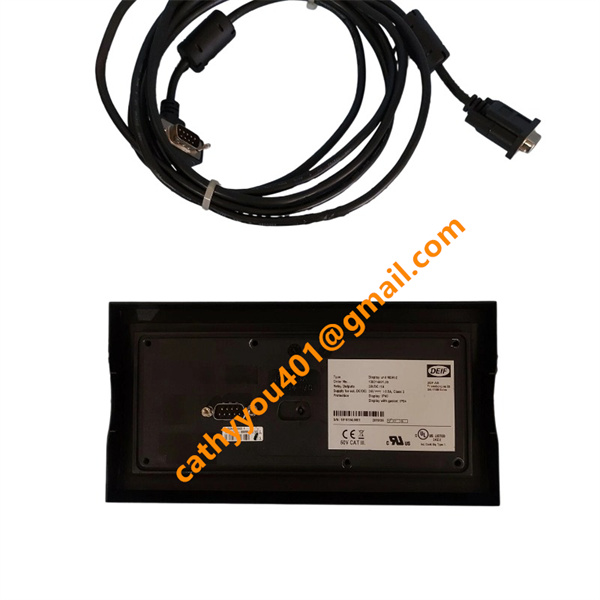
Link the display port of the main unit to the DU-2 remote display via a dedicated SUB-D cable, available in 1m, 3m and 6m lengths. The remote display requires no separate power supply.
Earthing Connection
Attach the unit’s chassis ground terminal to the cabinet protective earth. Collect shielding wires from CT secondary cables and communication cables to a unified grounding point to suppress electromagnetic interference.
Post-Wiring Check
Verify correct polarities for power and CT wiring; make sure no terminal short circuits exist. Tighten all terminal screws securely. Route power cables and signal cables separately to minimize electromagnetic interference.