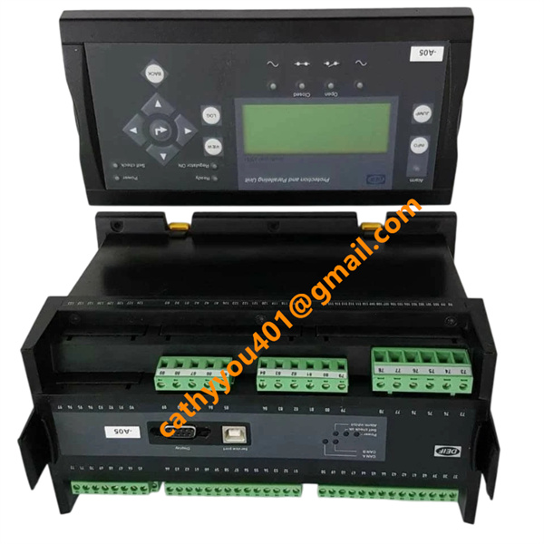






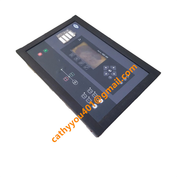

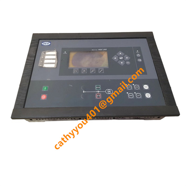







Description
-
BrandDEIF
-
ModelAGC 245
-
Product NameAdvanced Multi-Line Genset Controller / Generator Power Management Controller
-
Country of OriginDenmark
-
HS Code8537101100
-
Dimensions230mm×160mm×65mm
-
Weight1.95kg
-
Operating Temperature-25°C to +70°C
-
Storage Temperature-40°C to +85°C
-
Power Supply24VDC
-
Warranty12 month
-
Product StatusNew and original
DEIF AGC 245 Product Introduction and Technical Specifications
Input Technical Parameters
Power Supply Input: Supports universal DC wide-range power supply of 12VDC and 24VDC, with stable power consumption lower than 0.5mA. It allows certain voltage fluctuation and transient impact, adapting to unstable power supply conditions of on-site genset battery systems.
Voltage and Current Sampling Input: Compatible with AC voltage sampling range of 100V to 690V, supporting standard -1/A and -5/A current transformer signal access. It features high-precision real-time collection of genset voltage, current, frequency and phase angle data to provide accurate basis for synchronization and load regulation.
Multi-Functional Analog Input: Equipped with 4-20mA analog signal input ports, compatible with PT100 temperature sensors and VDO sensors, realizing real-time monitoring of engine temperature, pressure and other operating parameters.
Digital Switch Input: Multiple isolated digital input terminals are configured to collect circuit breaker status, external interlock signals, fault reset signals and engine operating state feedback signals, realizing comprehensive status monitoring of power system equipment.
Output Technical Parameters
Relay Control Output: Built-in multi-channel relay outputs with 12A fuse protection and UL certified 250VAC/DC 6A load capacity. It can directly control genset start-stop, breaker closing and tripping, and external executive equipment with stable and reliable driving capability.
Alarm and Status Output: Programmable multi-channel alarm output, which can send out fault alarm, overload prompt, synchronization completion and system abnormal signals to realize real-time fault warning and status indication.
Communication Output: Supports multiple industrial communication methods including CAN bus, Ethernet and GSM. It realizes remote parameter configuration, real-time operating data upload, fault record storage and SMS alarm push, and can be seamlessly connected with upper computer monitoring systems and DCS platforms.
Data Recording Output: Equipped with SD card data storage function, supporting long-term lifetime operation data and fault event recording, which is convenient for subsequent equipment operation analysis and fault tracing.

AGC 245 DEIF Product Core Advantages
Intelligent Integrated Control: Integrates genset automatic start-stop, mains failure switching, grid synchronization, parallel operation, load management and multi-level fault protection in one device, replacing multiple traditional discrete control modules. It simplifies the power control system structure and reduces equipment investment costs.
High Operation Reliability: Adopts industrial-grade hardware components and DEIF’s self-developed mature control algorithm, with strong anti-electromagnetic interference ability. It supports hot standby redundancy and multi-master parallel operation, effectively avoiding system single-point failure and ensuring continuous and stable power supply of generator sets.
Precise Power Management Performance: Realizes accurate active and reactive load distribution among parallel gensets, with high synchronization precision and fast response speed. It effectively optimizes genset operating efficiency, reduces fuel consumption, and avoids unbalanced load operation and equipment overload risks.

AGC 245 DEIF Wiring Method
The DEIF AGC 245 adopts rear terminal block centralized wiring design with clear functional zoning, including power supply wiring area, AC sampling wiring area, digital input wiring area, relay output wiring area and communication wiring area, realizing standardized and orderly on-site wiring construction.
For power supply wiring, connect the 12VDC or 24VDC on-site battery power supply to the dedicated power terminals, strictly distinguish positive and negative poles, and ensure firm wiring to avoid loose contact caused by equipment vibration. For AC signal sampling wiring, connect voltage and current transformer secondary lines to corresponding sampling terminals in strict accordance with phase sequence and polarity, and use shielded cables for wiring and standard grounding treatment to eliminate electromagnetic interference.
For sensor and analog wiring, connect temperature and pressure sensors to analog input terminals according to signal specifications to complete engine parameter collection. For digital signal wiring, access on-site breaker status, interlock and reset signals to digital input terminals to realize system status monitoring.
For control and alarm output wiring, connect relay output terminals to genset start-stop circuits, breaker control loops and on-site alarm devices to complete automatic control and alarm functions. For communication wiring, select CAN bus or Ethernet connection according to system requirements to realize remote monitoring and data transmission.
After all wiring is completed, conduct comprehensive circuit inspection, insulation test and signal simulation debugging. Calibrate synchronization parameters, load distribution logic and protection threshold values, and perform trial operation to ensure the controller’s automatic control, protection and communication functions operate stably and accurately.