





112BD2B222E14D96B59F6F6E51FA8842.jpg)
.jpg)







Description
-
BrandABB
-
ModelPE1315A
-
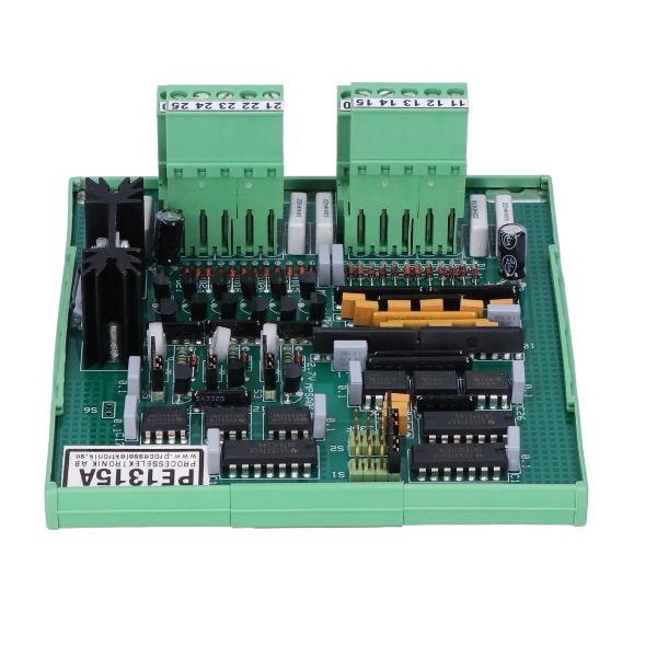
Product NameOpto Isolated Pulse Amplifier
-
Place of OriginSweden
-
Customs HS Code853890
-
Part number5FSE707630-7
-
Dimensions110 mm × 112 mm × 65 mm
-
Weight0.55 kg
-
Operating Temperature-20℃ ~ +60℃
-
Storage Temperature-40℃ ~ +85℃
-
Warranty12 month
-
Product Statusoriginal
Technical Specifications of ABB PE1315A (5FSE707630-7)
The PE1315A is an opto-isolated pulse amplifier module with DIN rail mounting, designed for galvanic isolation, signal splitting and amplification of pulse signals.
Channel configuration
It contains 3 independent channels: Channel A, Channel B and Strobe channel. It supports both complementary and non-complementary pulse input signals.
Electrical specifications
Input voltage range: 5~24V DC
Output voltage range: 5~24V DC
Output current: 13mA per channel
Galvanic isolation voltage: 2500V between the input side and output side
Mechanical & installation
Mounting method: standard DIN rail installation
Protection class: IP20, suitable for indoor cabinet installation
Function features
It adopts optocoupler isolation architecture to eliminate ground loop interference. The module accepts pulse train signals from encoders or pulse generators and executes isolation, amplification and signal distribution.
Application
It is used for isolation and transmission of encoder pulse signals within speed measurement, position tracking and rotary measurement systems. It is widely adopted in metallurgy, paper machinery and power industries.
Signal characteristics
It processes pulse signals from incremental encoders. It isolates and transmits quadrature A/B and strobe marker signals while preserving signal integrity without waveform distortion.

Pre-check & Safety Preparation
Carry out lockout-tagout and cut off power prior to inspection. Wear an anti-static wristband to avoid electrostatic damage. Confirm all wiring terminals are tightly secured and inspect the DIN rail mounting status. Prepare a multimeter and oscilloscope for pulse signal measurement.
Power Supply Inspection
Measure the DC input voltage supplied to the PE1315A and ensure it falls within the 5~24V DC range. Check for loose terminals, voltage drop and power ripple. Low or fluctuating supply voltage may lead to unstable pulse output or channel dropouts. Verify that the power source provides adequate current capacity.
Input Signal and Wiring Check
Examine encoder pulse wiring for Channel A, Channel B and the Strobe channel. Inspect cables for integrity, short circuits or open circuits. Confirm the signal type complies with module specifications (complementary or non-complementary pulse signals). Use an oscilloscope to observe input pulse waveforms and check for signal attenuation, distortion or noise caused by ground loops. Route pulse cables separately from high-power cables to mitigate EMI interference.
Channel-by-channel Signal Test
Test each channel individually. Inject a pulse signal into one channel and monitor its corresponding output. If only a single channel malfunctions, troubleshoot the wiring and input device for that specific channel. If all channels produce no output, inspect the module power supply and shared input wiring. Ensure no overload occurs on the output circuit; each channel has a 13mA output current limit.
Isolation and Ground Loop Troubleshooting
The PE1315A utilizes optocoupler galvanic isolation. In cases of signal jitter or abnormal fluctuations, check the ground potential difference between the encoder side and controller side. Remove multiple grounding points to eliminate ground loop noise. Validate isolation integrity, as high common-mode voltage can damage the internal optocoupler.
Environmental and Mechanical Inspection
Check the cabinet ambient temperature, which should stay within the operating range of -20°C ~ +60°C. Excessive heat, heavy dust or vibration can trigger intermittent faults. Inspect the module for physical damage, burn marks or terminal corrosion. Verify adequate ventilation clearance around the DIN rail.
Output Side Verification
Measure the output pulse waveform at the PE1315A output terminals. Confirm the output pulses track input pulses without phase shift or missing pulses. If the input pulse is normal yet no output signal appears, the module’s opto-isolation circuit may be defective. Ensure the receiving controller terminals can reliably capture 5~24V pulse signals.
Swap Test for Fault Localization
Replace the PE1315A with a verified good spare module. If the fault moves to the new module’s location, the root cause resides in field wiring or the encoder. If the fault disappears after replacement, the original PE1315A module is defective. This method quickly differentiates module failure from faults in field equipment.
Common Fault Handling
No output pulse: Check power supply, open cables, encoder failure or damaged optocoupler.
Pulse loss / unstable pulse: Ground loop interference, poor terminal contact, insufficient power or signal attenuation over long cables.
Intermittent channel dropout: Loose wiring induced by vibration, overtemperature or marginal supply voltage.

FAQ of ABB PE1315A 5FSE707630-7
Q: Can you export ABB PE1315A 5FSE707630-7 to overseas countries?
A: Yes, we provide full export service including commercial documents, anti-static shockproof packaging and global shipment for industrial automation customers.
Q: What payment terms do you accept for bulk orders of PE1315A?
A: T/T is our standard payment term. Negotiable terms are available for large EPC project orders. We can issue commercial invoice, packing list and complete export documents.
Q: What shipping options are available for ABB PE1315A 5FSE707630-7?
A: Air freight and sea freight are available. We ship from Xiamen, Shanghai, Shenzhen and other major China ports.
Q: What is the delivery time of PE1315A 5FSE707630-7?
A: In-stock items can be shipped within 1–3 working days. Lead time for out-of-stock modules depends on ABB supply schedule, we will confirm before order placement.

GDB021BE
Unitrol 1020
698B275U01
SM810K01
BC810K02
PP886
PBA800
RED615


.jpg)

.jpg)
.jpg)
.jpg)







