





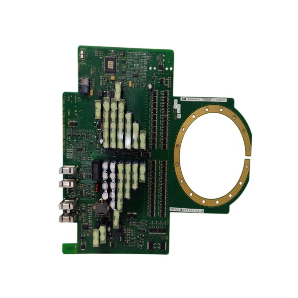







Description
-
BrandABB
-
ModelGVC736CE101
-
Product NameGVC736CE101 Converter Board
-
Place of OriginSwitzerland
-
Customs HS Code85389000
-
Part number3BHE039204P201
-
Dimensions220mm × 130mm × 22mm
-
Weight0.36kg
-
Operating Temperature-20°C to +60°C
-
Storage Temperature-40°C to +85°C
-
Warranty12 month
-
Product Statusbrand new
ABB 3BHE039204P201 Technical Parameters
Product type: IGCT gate drive unit, compatible with ABB IGCT power semiconductors for medium voltage power conversion systems
Power supply: 24 VDC auxiliary power
Core function: Produces gate trigger and turn‑off pulses for IGCTs; carries out device status supervision and fault detection
Interface type: Fiber optic communication ports for transmitting trigger commands and status feedback signals
Isolation characteristic: High galvanic isolation separating low‑voltage control circuitry from the high‑potential power side
Diagnostic function: Real‑time monitoring of auxiliary supply voltage, gate pulse integrity, device faults and fiber link failures; fault messages transmitted over optical channels
Relative humidity: 5% ~ 95%, non‑condensing
Cooling method: Natural convection cooling
Communication: Fiber optic links to receive switching orders from the control board and report operating status
Application system: ABB medium voltage converters, static var compensators, medium voltage drives and power quality control equipment
Certifications: CE marked, compliant with industrial EMC standards
Mounting form: PCB assembly, fitted inside the power unit cabinet
Fault response: Instantly inhibits gate drive signals when critical faults are detected to safeguard power semiconductor devices

ABB 3BHE039204P201 Installation and Commissioning Guide
Part number: 3BHE039204P201
Product type: IGCT gate drive unit for medium voltage power conversion systems
1. Pre-installation Preparation
Inspect the unit for physical integrity, checking the PCB for scratches, burn marks and damaged fiber optic ports. Confirm compatibility with the matched IGCT power device and control board. Prepare insulated tools, optical fibers, a multimeter, an oscilloscope and an anti-static wristband. Verify the cabinet environment satisfies specified temperature and humidity limits, and is free from conductive dust and corrosive gases. Ensure all high-voltage circuits are completely discharged before carrying out any work.
2. Mechanical Installation
Install the PCB drive unit at its designated position within the power unit cabinet. Reserve adequate clearance for natural convection cooling and do not obstruct airflow paths. Fasten the board using recommended fixings with appropriate torque to prevent PCB distortion. Route optical fibers separately from high-current power cables to minimize electromagnetic interference.
3. Electrical and Optical Wiring
Wire the 24 VDC auxiliary control supply to the dedicated terminals and strictly verify polarity. Fit optical fiber links between this gate drive board and the master control board. Differentiate command-receiving fibers and status feedback fibers, and avoid bending fibers below their minimum bending radius. Confirm all connectors are fully engaged and locked. Segregate low-voltage control wiring from high-potential power circuits to maintain galvanic isolation performance.
4. Static Inspection (Main High Voltage Power Disconnected)
Use a multimeter to test for short circuits on the 24 VDC power bus and gate drive output terminals. Confirm there is no short between the drive circuitry and power ground. Check fiber link continuity and ensure no light leakage occurs. Isolation resistance tests for the main power circuit must be performed with the gate drive auxiliary power disconnected to avoid circuit damage.
5. Auxiliary Power-on Static Commissioning
Energize only the 24 VDC auxiliary supply while the medium-voltage main power remains off. Check the power indicator of the drive unit and confirm normal operation of internal power regulation circuits. Send test optical trigger signals from the control board and monitor fault feedback signals returned by the drive unit. Use an oscilloscope to validate the amplitude, edge characteristics and noise level of gate trigger and turn-off waveforms, ensuring compliance with IGCT device specifications.
6. Function and Fault Logic Test
Simulate diagnostic events such as auxiliary supply undervoltage, loss of optical link and gate pulse failure. Confirm the drive unit immediately inhibits gate signals and transmits corresponding fault codes through the optical channel. Validate that fault latching and reset logic conform to the system protection scheme.
7. No-load Commissioning with Main Power
Apply medium-voltage main power while the system remains mechanically unloaded. Operate the converter at low frequency and low voltage. Monitor real-time drive status, optical communication integrity and IGCT switching performance. Record the operating temperature of the drive board and check for excessive heat or intermittent faults.
8. Load Commissioning and Parameter Verification
Increase the load gradually from light load to rated operating conditions. Continuously monitor drive waveforms, component temperatures and fault status. Confirm overcurrent, overvoltage and communication fault protections activate rapidly as designed. Record commissioning data and fault logs.
9. Post-commissioning Check and Handover
Conduct a continuous stability test with the system running at rated conditions. Confirm all protection functions and communication interfaces operate reliably. Clean fiber connectors and remove dust from the cabinet. File test reports, waveform records and parameter configurations for documentation.

GDB021BE
Unitrol 1020
698B275U01
SM810K01
BC810K02
PP886
PBA800
RED615


.jpg)
.jpg)
.jpg)







