





.jpg)







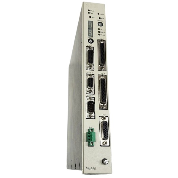
Description
-
BrandABB
-
Model3BHB027204R0001
-
Product NameHigh Performance Control Module
-
Place of OriginSwitzerland
-
Customs HS Code85389000
-
Power Supply19.2 VDC ~ 26.4 VDC
-
Dimensions220mm × 130mm × 30mm;
-
Weight0.75 kg
-
Operating Temperature-40℃ ~ +70℃
-
Storage Temperature-56℃ ~ +99℃
-
Warranty12month
-
Product Statusnew and original
Debugging Procedure for ABB 3BHB027204R0001
This component serves as the communication and logic processing board for ABB medium voltage drives. Comply with all safety requirements prior to starting any work.
Safety preparation
Disconnect all high voltage and auxiliary power supplies of the drive cabinet;
Allow a minimum 15-minute waiting period for capacitor discharge;
Use insulated tools and wear an anti-static wristband;
Perform visual inspection for obvious defects including burn marks, loose connectors and cracked PCBs.
Hardware inspection
Reinstall the board securely into its rack slot;
Examine backplane connectors, fiber optic links and Ethernet cables;
Validate the 24VDC auxiliary power supply to the board and check voltage ripple;
Ensure no short-circuit exists on power pins.
Power-on low-voltage test (main high voltage disconnected)
Apply only 24VDC control power;
Observe LED status indicators on the board;
Document LED colours and flash patterns;
Retrieve fault codes using ABB drive software or local control panel;
Verify board identity, firmware revision and communication status.
Communication debugging
Validate backplane bus communication between this board and other drive control boards;
Measure transmit and receive signal strength of fiber optics;
Test Ethernet connection if equipped;
Confirm normal data exchange between the logic board and drive power unit.
Parameter & configuration check
Restore the original backup project of the drive;
Validate board station address and drive topology configuration;
Review drive control parameters, protection limits and feedback signal scaling;
Flash the matching firmware if version incompatibility is detected.
Dry-run test (motor unloaded)
Main high voltage remains disconnected;
Switch the drive into test mode;
Send control commands and monitor real-time measurement signals;
Test interlock logic, fault tripping and alarm response;
Clear historical fault records after verification.
On-load commissioning
Reconfirm all safety interlocks before energising main high voltage;
Power on the drive in stages;
Monitor board temperature, bus communication and signal stability during operation;
Conduct motor no-load test, then ramp up load gradually;
Save all operating logs and fault records.
Final check
Confirm all alarms are reset and communication maintains stability;
Create backup for updated firmware and parameter files;
Refit cabinet covers and finish the commissioning report.
Communication Protocol & Parameter Settings for ABB 3BHB027204R00011. Communication Protocols
1.1 Internal Backplane Bus (Primary On-Rack Communication)
Protocol: ABB proprietary high-speed serial backplane bus, specially designed for internal communication within the MV drive rack.
Function: Real-time cyclic data exchange between this logic board, rectifier unit, inverter power cells and other control boards.
Features: High real-time performance and strict cycle synchronization; transmits voltage, current, temperature, cell status, interlock and fault signals.
Transmission medium: Gold-plated connectors on the rack backplane; no external wiring required.
Failure impact: Loss of backplane communication will trigger drive interlock trip and communication timeout fault.
1.2 Fiber Optic Communication (Power Cell Link)
Protocol: ABB proprietary optical serial protocol.
Medium: Multi-mode fiber optic cables.
Purpose: Provide galvanically isolated communication between the logic board and power units to suppress high-voltage interference.
Data content: Cell voltage, cell temperature, pulse commands and fault status of each power module.
Key check items: Optical transmit/receive power, fiber attenuation, fiber bend radius and connector cleanliness.
1.3 External Ethernet Interface (For PC Tool & Upper Control)
Protocol: TCP/IP plus ABB proprietary drive service protocol for commissioning, firmware download and parameter backup.
Optional upper host protocols (subject to complete drive configuration): Modbus TCP and IEC 61850 (supported only if the whole drive package is equipped).
Speed: 100 Mbps.
Use case: Connect ABB PC commissioning tool for parameter read/write, fault log upload and firmware upgrade.
Notices: This Ethernet port is mainly reserved for commissioning. Do not directly connect it to an unprotected factory network without a firewall.
1.4 Optional Fieldbus (Depends on Drive Option Card)
This board itself does not implement Profibus DP / Profinet / Ethernet/IP directly. It exchanges data with the external fieldbus adapter through the internal backplane bus. The external fieldbus protocol is processed by a separate fieldbus card, while 3BHB027204R0001 handles internal data mapping.
2. Core Communication Parameter Settings
2.1 Board Station Address (Critical Item)
Parameter name: Board node / station address on backplane bus.
Setting rule: A unique address must be assigned within the entire drive rack; duplicate addresses are prohibited.
Setting method: Configured via commissioning software or PCB DIP switches (some firmware versions adopt software assignment only).
Consequence of incorrect setting: Bus conflict, unidentifiable board and continuous communication alarms.
2.2 Backplane Bus Cycle Time
Function: Define the cyclic data refresh interval among rack boards.
Range: Fixed or configurable based on the drive power rating.
Recommendation: Retain factory default values; adjustments can only be approved by senior ABB engineers.
Too short cycle: Increased bus load and communication jitter. Too long cycle: Delayed protection response.
2.3 Ethernet IP Parameters (For Commissioning Port)
IP address: Configured within the same subnet as the laptop commissioning tool.
Subnet mask: 255.255.255.0 (common default value).
Gateway: Leave blank for direct point-to-point connection with PC.
Communication timeout: Specify the maximum silent duration before the board reports Ethernet link loss.
MAC address: Fixed hardware MAC address, non-modifiable.
2.4 Optical Communication Threshold Parameters
Optical receive power threshold: Minimum acceptable optical signal strength.
Signal loss alarm threshold: Activate warning when fiber attenuation exceeds the limit.
Communication retry count: Maximum retry attempts upon optical data packet errors.
Packet error monitoring: Record CRC error counts for fiber diagnostics.
2.5 Data Mapping Parameters
Signal mapping: Map internal drive signals (current, voltage, frequency, ready, fault, alarm) to backplane bus registers.
Scaling parameters: Convert raw ADC measurement data into engineering values (A, V, ℃).
Logic interlock mapping: Enable or disable hardware and software interlock signals transmitted over the internal bus.
3. Drive & Logic-Related Parameters on This Board
Board identification & firmware parameters: Board type code, firmware version and serial number. The firmware must match the MV drive system version; version mismatch leads to board rejection and startup failure.
Protection threshold parameters: Power unit over-temperature threshold, communication fault trip delay and watchdog timeout. The board monitors the bus watchdog, and watchdog timeout triggers immediate drive trip.
Fault & alarm configuration: Enable or disable individual alarms, fault latch mode, fault reset logic and fault record storage depth.
Topology configuration: Power cell quantity, series/parallel power unit topology and rack hardware configuration matching. The board verifies hardware topology during power-up, and topology mismatch prevents drive readiness.
4. Parameter Setting Procedure
Complete hardware inspection and low-voltage 24VDC power-up with main high voltage disconnected.
Connect the PC and ABB commissioning tool via Ethernet.
Establish communication and read the existing parameter backup file.
Verify the board station address and rack topology, then correct duplicate or incorrect node addresses.
Check optical communication threshold and bus cycle parameters.
Modify mapping and protection parameters strictly according to the approved project file.
Download parameters to the board, save and back up the complete parameter set.
Reboot the board, confirm parameter activation and eliminate communication alarms.
Conduct dry-run test to validate signal exchange and interlock logic.
Record all modified parameters in the commissioning document.
5. Common Communication Faults & Parameter Troubleshooting
Board cannot be scanned: Incorrect station address, poor backplane contact, abnormal 24VDC supply or firmware version mismatch.
Intermittent fiber communication alarm: Optical power below threshold, dirty fiber connector or excessive fiber bending.
Watchdog timeout: Improper bus cycle configuration, high bus load or hardware failure of another rack board.
Parameter download failure: Mismatched Ethernet IP, unstable 24V power or firmware incompatibility.
Random signal fluctuation: Wrong signal scaling parameters, poor EMC grounding or loose backplane contact.
6. Important Warnings
All parameter modifications shall be performed by qualified ABB-certified personnel.
Back up original parameters before making any changes.
Do not arbitrarily adjust backplane bus cycle and protection threshold parameters; improper settings may result in equipment damage or safety risks.
All high-voltage operations must comply with local safety lockout procedures.

FAQ for ABB 3BHB027204R0001
1. What is ABB 3BHB027204R0001 used for?
ABB 3BHB027204R0001 is a rack-mounted control & communication board designed for ABB medium voltage variable frequency drives. It handles internal bus communication, signal feedback collection and logic processing between main controller, I/O cards and upper control system, widely used in power, metallurgy, chemical and pulp & paper industries as spare parts for MV drive maintenance.
2. Is 3BHB027204R0001 still in production by ABB?
This model is an older spare part for medium voltage drives, ABB has stopped original mass production. We supply in-stock new surplus, tested refurbished units for replacement. Please contact us to confirm real-time stock status.
3. What condition options do you offer for ABB 3BHB027204R0001?
We have multiple options: new unused surplus stock, fully tested refurbished modules. All units will go through function testing before shipment and come with test report.
4. What is your warranty term for 3BHB027204R0001?
We provide 12 months warranty for this ABB module, valid from the date of delivery. Warranty covers hardware functional failure under normal installation and operation. Damage caused by improper installation, overvoltage or physical impact is excluded.
5. How long is the lead time for ABB 3BHB027204R0001?
If the item is in stock, shipment can be arranged within 1–3 working days. For out-of-stock requests, we will quote estimated lead time separately. We support urgent shipment for emergency downtime cases.
6. Can you help check compatibility of 3BHB027204R0001 with my existing ABB MV drive?
Yes. Please provide your full drive model and serial number. Our technical team will verify compatibility before order to avoid mismatched spare parts.

GDB021BE
Unitrol 1020
698B275U01
SM810K01
BC810K02
PP886
PBA800
RED615


.jpg)

.jpg)
.jpg)







