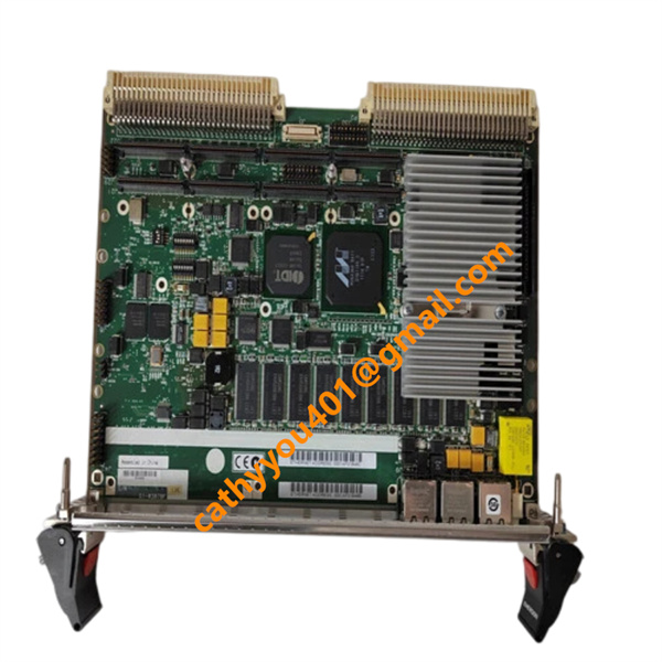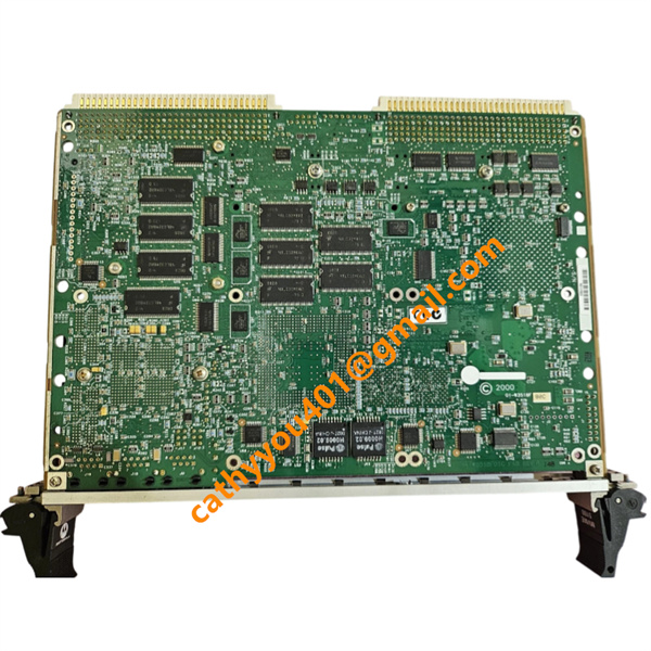






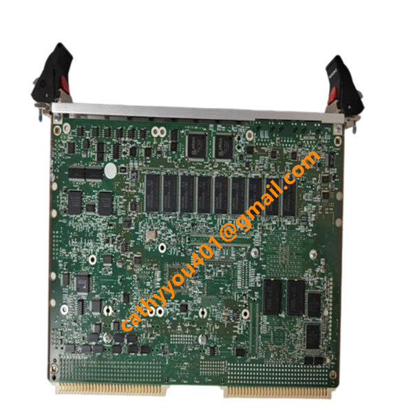







Description
-
BrandMotorola
-
ModelMVME61006E‑0163R
-
Product Name6U VME64x Single-Board Computer
-
Place of OriginUnited States
-
HS Code85423190
-
Dimensions8.25 inches × 9.5 inches × 4.5 inches
-
Weight0.36 kilograms
-
Operating Temperature0°C to +55°C
-
Storage Temperature-40°C to +85°C
-
Power Supply24VDC
-
Warranty12 month
-
Product StatusNew and original
Motorola MVME61006E‑0163R Voltage & Current Detailed Specifications
1. Input Voltages from VME Backplane
The board obtains power through the P1 and P2 connectors of the VME64x backplane with three standard power rails:
+5V DC (±5% tolerance): Main power supply that sustains the entire single-board computer
+12V DC: Auxiliary power for onboard I/O circuits and PMC expansion interfaces
-12V DC: Auxiliary power dedicated to analog serial communication circuits
All internal working voltages for onboard chips are produced by built-in DC-DC converters, which take power exclusively from the +5V input rail.
2. Internally Regulated Voltage Outputs
Onboard power conversion circuits supply stable voltages to CPU, memory, bus controllers and logic devices:
+3.3V: For I/O buffers, PCI-X bus and gigabit Ethernet controllers
+2.5V: Reference voltage for DDR memory modules
+1.8V: Auxiliary supply rail for the MPC7457 processor
Dynamic core voltage for MPC7457: Automatically adjusted according to real-time CPU workload
3. Current Consumption of Main +5V Rail
Bare board (without any PMC mezzanine cards mounted)
Typical operating current: 8.4 A
Peak maximum current (CPU and all I/O running at full load): 10.2 A
Equipped with two fully functional PMC daughterboards
Typical operating current: 9.2 A
Peak maximum current: 11.2 A
The +12V and -12V auxiliary rails only carry tiny currents for signal-level circuits and do not support high-power loads.

Wiring Method of Motorola MVME61006E‑0163R
VME Backplane Power & Bus Wiring
This 6U VME single-board computer connects to a VME64x backplane through rear 5-row 160-pin P1 and P2 DIN connectors. P1 carries basic VME bus signals, while P2 delivers extended bus signals and power supplies (+5V, +12V, -12V and ground). The board draws all power from the backplane without separate power ports; onboard DC-DC converters convert +5V into internal operating voltages (+3.3V, +2.5V, +1.8V). Insert the card into a VME slot, secure ejector latches and front panel screws for solid electrical contact.
Front Panel External Interface Wiring
Dual Gigabit Ethernet (RJ45 J9/J93): Link Cat6 shielded cables to industrial switches. Jumper J30 switches signal paths between front panel and rear P2.
COM1 debug serial port (RJ45 J19): Use an RJ45-to-DB9 cable to connect a PC terminal for debugging, complying with standard RS232 wiring.
COM2: Accessible via onboard J29 pin header, connected to secondary serial devices with custom flying leads.
PMC Mezzanine Expansion Wiring
Two PMC-X slots (PMC0 J11/J14, PMC1 J21/J24) use standard 64-pin PN1-PN4 connectors for vertical PMC daughterboard installation. PCI-X power, interrupt and data signals transmit via gold fingers. Jumpers J10/J15-J18 toggle two modes: PMC mode routes partial I/O to rear P2 for transition modules; IPMC mode supports MVME761/MVME712M legacy rear I/O boards.
Debug & Configuration Header Wiring
J42 16-pin JTAG/COP header: Attach special download cables for firmware programming and boundary scan tests.
J7 SCON header: Set the board as VME master or slave by shorting specific pins with jumpers.
J8 Boundary Scan header: Pair with test cables for factory hardware fault inspection.
S3/S4 DIP switches: Manually toggle to adjust boot flash and startup settings, no wiring needed.
Wiring Specifications & EMC Guidelines
Deploy shielded cables for Ethernet and serial ports, grounding cable shields at the chassis end to cut electromagnetic interference.
Verify 3.3V default keying pins match PMC module voltage to prevent component damage.
Ensure complete ground continuity on the VME backplane to stabilize the +5V main power rail.
The R variant integrates built-in power filters, eliminating extra surge suppression wiring.