





.jpg)
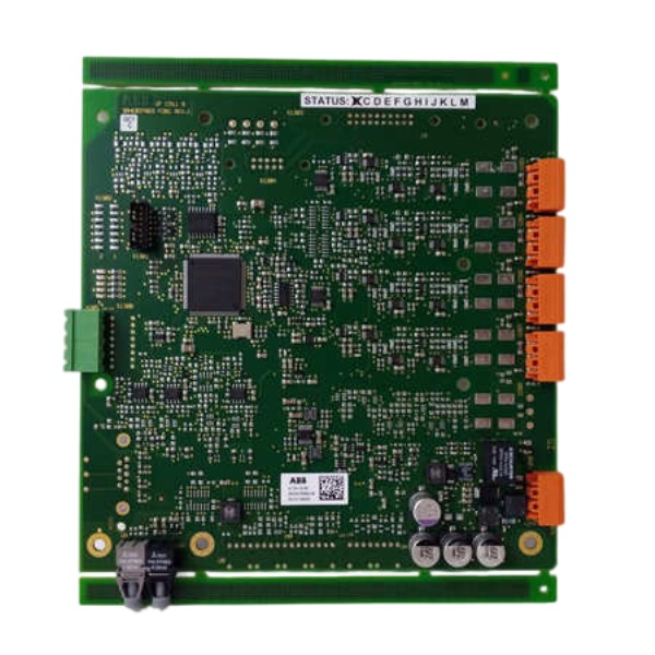







Description
-
BrandABB
-
ModelUFC911B108
-
Product NameExcitation System Control Interface Board
-
Place of OriginSwitzerland
-
Customs HS Code85371011
-
Part number3BHE037864R0108
-
Dimensions119 mm × 106 mm × 44 mm
-
Weight0.48 kg
-
Operating Temperature-20°C to +70°C
-
Storage Temperature-50°C to +80°C
-
Warranty12 month
-
Product Statusnew and original
Key Features of ABB 3BHE037864R0108 (UFC911 B108)
This unit functions as the main drive control board for ABB medium-voltage drive systems, with compatibility covering ACS1000, ACS6000 and high-power ACS800 drive series.
It implements Direct Torque Control (DTC) and vector control algorithms, providing high-speed real-time motor control for both induction and synchronous motors.
It handles system sequential logic, multi-layer drive protection, as well as internal coordination among power units, cooling assemblies and human-machine interfaces.
The high-performance processing platform enables rapid control-loop computation to satisfy stringent real-time demands of high-power converter applications.
Multiple embedded hardware protection mechanisms cover over-current, over-voltage, overload and temperature supervision, which initiate interlock responses promptly once abnormal operating conditions occur.
It adopts an internal high-speed parallel bus to communicate with power modules, while the external Modbus-RTU serial interface enables data exchange with DCS and superior monitoring systems.
Comprehensive on-board diagnostic capabilities store fault codes and operational event records, facilitating on-site troubleshooting and post-incident analysis.
Adopting compact rack-mount design for installation inside control cabinets, it simplifies system assembly and spare-part replacement work.
Equipped with superior EMC anti-interference performance, it maintains stable operation under harsh industrial conditions and fits heavy-duty applications including metallurgy, mining, water supply, large-scale fans and pumps.
It supports distributed control framework and can coordinate multiple rectifier and inverter units within high-power multi-module drive systems.
Firmware can be upgraded to realize feature enhancement and hardware compatibility optimization.

Installation and Commissioning Steps for ABB 3BHE037864R0108 (UFC911-B108)
Pre-Installation Safety & Inspection
Cut off all high-voltage and control power and perform lockout-tagout procedures, ensuring full capacitor discharge inside the drive cabinet.
Inspect the module surface for mechanical damage, bent pins, burnt circuit traces and deformed connectors, and confirm the part number 3BHE037864R0108 complies with the project BOM.
Examine rack backplane connectors for dust, oxidation and poor contact status, and ensure clean cabinet environment and unobstructed ventilation without conductive debris.
Mechanical Installation
Insert the UFC911-B108 module into the specified slot of the standard AC800PEC rack and push firmly for full engagement with backplane connectors.
Tighten module locking screws properly to prevent loose contact caused by operational vibration, avoiding over-tightening.
Reserve adequate airflow clearance around the module and keep it away from high-power heat sources.
Electrical & Fiber-Optic Wiring
Wire the 24 V DC control power strictly following polarity requirements; prohibit high-voltage access to control terminals.
Separate high-voltage power cables from low-voltage control cables and fiber cables to minimize electromagnetic interference.
Deploy LC single-mode fiber cables between the UFC911-B108 and power unit boards, maintain a minimum fiber bend radius of 40 mm, and avoid sharp bending and extrusion.
Terminate communication buses in strict accordance with design drawings, and complete shielding grounding for all shielded signal cables.
Perform full inspection of all connectors to ensure firm insertion without floating or misaligned pins.
Static Test (De-energized Power Section)
Energize only the 24 V DC control power while keeping the main high-voltage power disconnected.
Check front-panel LED status: normal power indication without persistent fault alarms.
Connect the PC with ABB Control Builder M software and establish stable module communication.
Read hardware information, verify hardware and firmware version compatibility with the entire drive system, and upgrade firmware if version mismatch exists.
Complete system configuration including fiber port mapping, power unit quantity definition, I/O allocation and basic DTC/vector control parameters, then download the project to module flash memory.
Conduct digital I/O simulation tests to verify consistency of interlock, enable and fault feedback logic with design specifications.
Check communication links between the UFC911-B108 and power units to eliminate fiber link errors, and clear all historical alarms and event logs.
No-Load Commissioning (Motor Disconnected)
Confirm the motor power cable is fully disconnected from inverter output terminals.
Energize the main power of the medium-voltage drive system.
Run system self-diagnosis, monitor fault codes and diagnostic information, and eliminate all hardware alarms before subsequent operations.
Input complete motor nameplate parameters including rated voltage, current, frequency, power and pole number.
Execute motor static identification to enable automatic calculation of internal motor parameters for control algorithm optimization.
Test inverter pulse output under motor disconnection status and check for pulse-related faults.
Calibrate and confirm all protection thresholds (over-current, over-voltage, overload, stall and over-temperature protection) meet system design standards.
On-Load Commissioning (Motor Connected)
Power down the system, correctly reconnect the motor power cable and recheck motor winding insulation resistance.
Switch to local control mode and perform low-frequency jogging test to check motor rotation direction, operating noise and vibration.
Run low-speed no-load operation, and monitor real-time motor current, voltage, torque and excitation status via the UFC911-B108.
Gradually increase the speed reference, verify full-speed no-load performance, and optimize DTC/vector control PI parameters for stable dynamic response.
Toggle between local and remote control modes to test start/stop, speed regulation, fault tripping and reset functions.
Simulate typical faults including over-current, fiber disconnection and power unit failure to validate interlock and protection response accuracy.
Verify upper computer communication via Modbus-RTU, ensure stable and accurate data interaction between the module and DCS/SCADA system.
Final Acceptance & Backup
Back up the complete configuration project and parameter files to local PC, and export all fault logs and operation records.
Archive optimized control parameters, motor identification data and protection settings into the official commissioning report.
Confirm all interlock logic fully conforms to project technical requirements.
Remove test equipment, restore cabinet configuration, and complete on-site handover and operator training.

GDB021BE
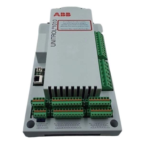
Unitrol 1020
698B275U01
SM810K01
BC810K02
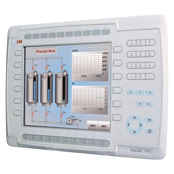
PP886
PBA800
RED615


.jpg)

.jpg)







